EXHAUST HEAT RECOVERY
Fume Incineration Systems
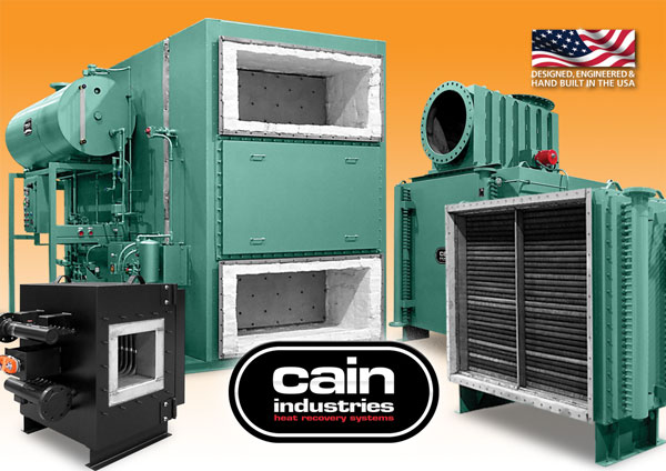
Exhaust Steam Generator Series - ESG
Heat Recovery Silencer Radial Series - HRSR
U-Tube Recovery 1 Series - UTR1
(exhaust heat recovery equipment shown from left to right)
“Manufacturing Waste Heat Transfer Products To Save Energy”
Since 1978, Cain Industries has dedicated itself to producing exclusively, combustion exhaust heat transfer products. Our successful experience with lowering fuel costs and reducing pollution makes us the first choice for both the retrofit and OEM client.
We set ourselves apart from the competition by producing products to serve the broad spectrum of the combustion retrofit markets: Diesel and Gas Cogeneration, Boiler Exhaust, and Fume Incineration. The knowledge we gain from each market helps the continuing improvement of the others. As the only manufacturer capturing these three markets, we have developed the greatest selection of products to precisely fit within their particular system applications. Coupled with our heat transfer programs and CAD engineered designs, we have developed fifteen product lines with over 2,350 pre-designed industrial heat transfer models.
We are also especially dedicated to a primary investment in our associates with their manufacturing technology, quality improvements, and innovative cost reductions. As a result, our customers can expect competitively priced products aimed at having the greatest return on their investment along with the longest lasting equipment.
The basic philosophy which Cain Industries has built its success and reputation upon is: "Produce the highest quality products and provide unmatched customer satisfaction."
John Cain
President & CEO
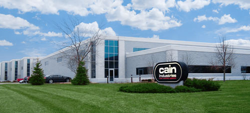
Cain Industries is 10 miles northwest of Milwaukee, Wisconsin and 30 minutes from General Mitchell International Airport.
ESG - EXHAUST STEAM GENERATOR
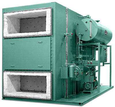
THE COMPLETE PACKAGE
Selecting the appropriate "waste heat boiler system" for fume incineration or cogeneration retrofit involves considerable engineering time and money. Important areas of concern have been controlling
and bypassing waste heat, optimum performance selection, operating pressures, size, weight and installation. The ESG is specifically designed to address these concerns and more, as standard design features not found with conventional waste heat boilers. The timely needs of the project engineer and customer can all be achieved accurately in a complete package.
VARIETY OF MODELS
Cain Industries offers 40 standard models achieving performance outputs from 20 to 500 boiler horsepower and operating steam pressures ranging from 3 to 450 PSIG. A packaged forced circulation watertube design, the ESG is manufactured and tested in accordance with the requirements of the ASME Boiler and Pressure Vessel Code and National Board.
FUNCTIONAL
As a fully automatic steam generator, the ESG responds immediately to fluctuating exhaust flows in conjunction with steam load demand swings. This allows the ESG to easily function as a supplemental or primary stream output station. For the very large waste exhaust systems, multiple generator arrangements can easily adapt effectively, without complex central controls.
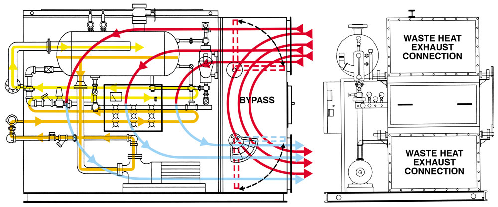
DESIGN
The ESG is a compact design including three basic sections: the finned tube heating surface, steam flash drum assembly, and a modulating full port exhaust bypass, pre-piped and wired for ease of installation and minimal customer connections. An integral circulating pump continually circulates water to the heat transfer section recovering BTU’s from the exhaust, and back to the steam drum assembly, where superheated water flashes to steam.
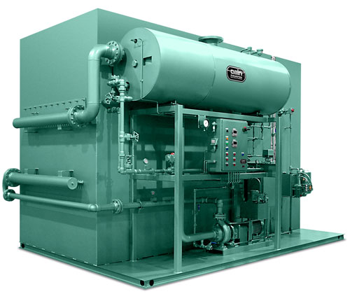 FEATURES
- Modulating Feedwater Valve Actuator
- Thermocouple Sensor (typical)
- Steam Flash Drum Assembly
- NEMA 4-Control Cabinet Assembly
- Circulating Pump Assembly
- Exhaust Bypass Assembly
- Steam Sense Transducer Controller
- Double Insulated Stainless Steel Bypass Dampers
- Inspection Tube Removal Exit Door
- Modulating Pneumatic Positioning Damper Actuator & Fail Safe Assembly
- 6" Structural Steel Skid
- 4" 250 lb. RF Flange Steam Outlet
- 1/4" x 2" x 2" Exhaust Flange Inlet & Outlet
- Main Power & Boiler Feed Connection
- 1-1/2" NPT Main Blowdown
- 1-1/4" NPT Feedwater Inlet
- 1/2" NPT Control Air
- 1/2" NPT Cooling Water Inlet & Outlet
- Boiler Blowdown Systems
- Boiler Feedwater Economizer
- Boiler Feed Condensate Return Systems
 ESG vs. CONVENTIONAL FIRETUBE BOILERS
- 1/3 - 1/2 the weight, size & floor space
- 99% dry steam
- 100% turndown capacity
- 5-10 minute startup to full output
- Integrated full exhaust modulating bypass
- "Explosion proof" heat transfer exchanger
- Low friction loss for minimum static exhaust back pressure
- High circulating flow minimizes scale buildup
- No thermal expansion problems: accepting cold water boiler feedwater
- Lowest "pinch point" (final leaving exhaust temperature minus operating steam temperature) offering greater thermal efficiency
- Liquid Phase Oil Heaters
- Hot Water Boilers
- Steam Superheaters
- Source of Exhaust Gas
- Temperature of Exhaust Gas
- SCFM or LBS/hr. of Exhaust Gas
- Operating Steam Pressure
- Desired Performance Output (either):
- PPH Steam
- BTU/hr. Transfer
- Leaving Exhaust Temperature
HRSR - HEAT RECOVERY SILENCER RADIAL
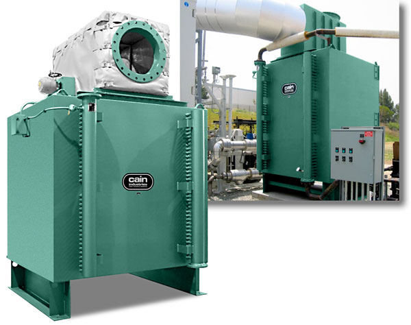
The HRSR (Heat Recovery Silencer Radial) Series is designed to receive total liquid flow, reduce gas temperatures to desired levels, and lower exhaust noise reducing the need for a muffler. The modulating exhaust bypass assembly will allow the tempering of exit temperatures to achieve optimal heat recovery. The radial design allows finned tube access for cleaning and inspection. A single row of finned tubing with optional removable Swagelok™ compression fittings, provides maximum thermal efficiency and easy access for cleaning, inspection or replacement.
The HRSR is engineered for vertical or horizontal operation, combustion capacity up to 4000kW, and entering gas temperature up to 1,250°F to match the needs of your specific application.
Combustion Sources
Incinerators, thermal oxidizers, catalytic converters, engines and boilers
Exhaust Application
Capacity: 500 to 20,000 SCFM
Entering Gas Temps: 450°F to 1,250°F
Heat Sink Types: engine jacket water, process water, boiler water and ethylene glycol
- Full Exhaust Bypass with Damper Assembly
- Modulating Actuator
- Liquid Manifold with Removable Compression Fittings
- Control Panel Assembly
- ASME Stamp (optional)
- Factory Insulation, Carbon Steel Exterior, Stainless Steel Interior
- Structural Support
ITR - INCINERATOR TUBE RECOVERY
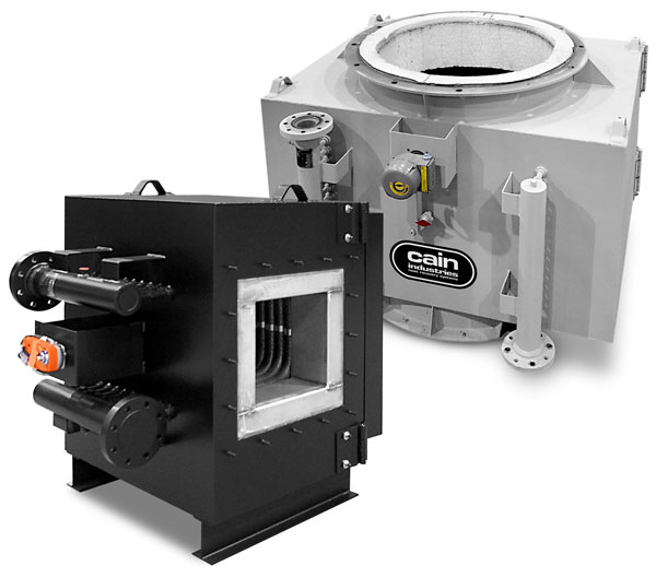
The ITR (Incinerator Tube Recovery) Series is specifically designed for high temperature exhausts. All gas side surfaces in contact with the exhaust are stainless and/or high temperature alloy. Combustion sources with round exhausts require optional stack transitions. Special fin spacing specifications can be offered dependent on fouling conditions. The internal gas bypass can be used to bypass heat (up to 70% dependent on the application) and temper water and/or the exiting gas temperatures.
Combustion Sources
Incinerators, thermal oxidizers and catalytic converters
Exhaust Application
Capacity: All Load Conditions
Entering Gas Temps: 1,250°F to 2,000°F
Heat Sink Types: process water, boiler feedwater, hot water return, potable water and hot oil
- 10 Gauge Structural Exterior
- High Temperature Alloy Interior
- 4" Factory Insulation
- High Temperature Alloy Internal Bypass
- No Pressure Welds in the Gas Stream
- Internal Thermal Expansion Design
- Mounting Flanges for Welding to Existing Stack or Adapters
- Removable Access Door
- Header Manifold for High Liquid Flow
- Compression Fittings for Tube Removal and Replacement
UTR1 - U-TUBE RECOVERY 1
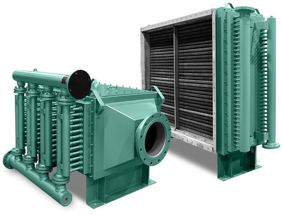
The UTR1 (U-Tube Recovery 1) is primarily used where maximum heat transfer is specified, and square or rectangular stacks along with confined area restrictions have to be addressed. The UTR1 is also selected when low liquid side pressure drops or gas side friction and shell side pressures (10" W.C.) are of concern. The UTR1 can be applied in cold water condensing heat exchangers for vertical or horizontal flue gas installation. The UTR1 is offered in stainless, carbon or AL-FUSE™ fin tubing with 4, 6, or 8 fins per inch spacing. With over 100 different face areas available ranging from 19" x 8" thru 131" x 72" and depths of 1, 2, 4, 6, and 8 rows. Many possible selections are available to choose from when a specific amount of surface area and/or a performance requirement must be met. All UTR1 assemblies bolt into the customers rectangular ducting flange (stack adapters may be required). The UTR1 can operate on No. 6 fuel oil (with carbon steel fin and tube with 4 fpi). Sootblowers available upon request.
- The UTR1 with 1 row is simply a weld core with liquid manifold connections at the opposite end of one another. The standard unit is uninsulated.
- The UTR1 with 2 rows is a removable welded core with the liquid manifold connections on the same side flange mounted within it's own frame. This design allows for the entire core to be removed from one side without disturbing the frame as it remains in the customer's duct work. The standard unit is uninsulated.
- The UTR1 with 4, 6, or 8 rows have individual fin tubing assemblies compression fitted to the liquid manifold connections on the same side. The standard unit comes with 2" thickness factory insulation and two access doors allowing for inspection and/or individual tube assembly removal capabilities requiring no welding.
Combustion Sources
Incinerators, thermal oxidizers, catalytic converters, boilers and hot oil heaters
Exhaust Application
Capacity: 200 to 50,000 SCFM
Entering Gas Temps: 450°F to 1,600°F
Heat Sink Types: process water, boiler feedwater, ethylene glycol, thermal transfer fluids
The UTR1 Parallel Flow is applied where a specific heat transfer requirement is needed at very high liquid flows, and square or rectangular stacks along with confined area restrictions have to be addressed. The UTR1 is offered in stainless, carbon, or AL-FUSE™ fin tubing with bare tube thru 8 fins per inch spacing selection flexibility. With over 100 different face areas available, unlimited rows deep, many possible selections adapt easily to the design needs. The capability of quickly removing fin tube rows or core assemblies from the shell, without disturbing the exhaust gas connections, reduces down time and allows for easy periodic inspection and cleaning as required.
- Parallel Header Manifold (High Liquid Flow) for Low Static Head
- Removable Core Bundle Assemblies
- Removable Inspection Access Door (Finned Tube Rack Assembly Access)
- Stainless Steel Interior
- Optional Exhaust Adapters with Mating Flanges
- Optional Access Door (Finned Tube Top Inspection and/or Cleaning)
- Factory Insulation 2" to 6" Thickness Available
The Giant UTR1 Series is applied where a very large heat transfer requirement is needed, and square or rectangular stacks along with confined area restrictions have to be addressed. The UTR1 is offered in stainless, carbon, or AL-FUSE™ fin tubing with bare tube thru 8 fins per inch spacing selection flexibility. With over 100 different face areas available, unlimited rows deep, many possible selections adapt easily to the design needs. The capability of quickly removing fin tube rows or core assemblies from the shell, without disturbing the exhaust gas connections, reduces down time and allows for easy periodic inspection and cleaning as required.
Features (Giant)- Inspection Door Assembly
- High Liquid Flow Header Manifold for Low Static Head
- Optional Access Door (Finned Tube Inspection and/or Cleaning)
- Factory Insulation 2" to 6" Thickness Available
- Removable Inspection Access Door (Finned Tube Rack Assembly Access)
- Heating Surface Face Area up to 180" Wide x 150" High
- Stainless Steel Interior
- Finned Tube Assembly (Nickel Brazed/Welded)
The UTR1 Series Flow is applied where a specific heat transfer requirement is needed, and square or rectangular stacks along with confined area restrictions have to be addressed. The UTR1 is offered in stainless, carbon, or AL-FUSE™ fin tubing with bare tube thru 8 fins per inch spacing selection flexibility. With over 100 different face areas available, unlimited rows deep, many possible selections adapt easily to the design needs. The capability of quickly removing fin tube rows or core assemblies from the shell, without disturbing the exhaust gas connections, reduces down time and allows for easy periodic inspection and cleaning as required.
Features (Series Flow)- Optional Exhaust Adapters with 150lb RF Flanges
- Optional Access Door (Finned Tube Inspection and/or Cleaning)
- Removable Inspection Access Door (Finned Tube Rack Assembly Access)
- High Liquid Flow Header Manifold for Low Static Head
- Factory Insulation 2" to 6" Thickness Available