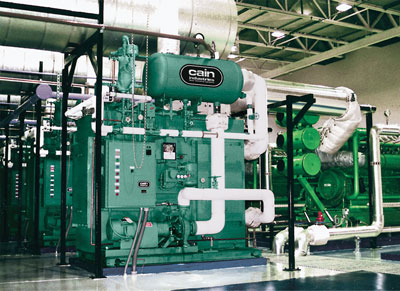
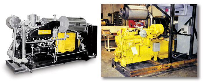
EXHAUST HEAT RECOVERY
Gas & Diesel Cogeneration Systems
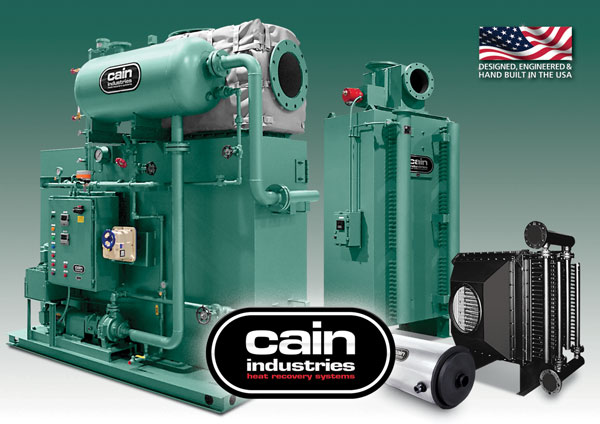
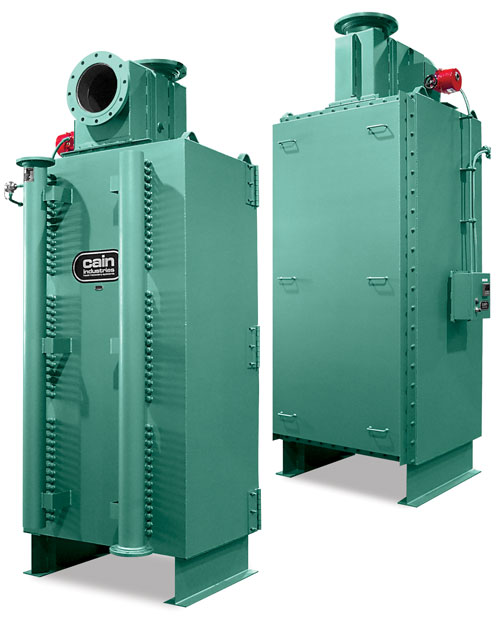
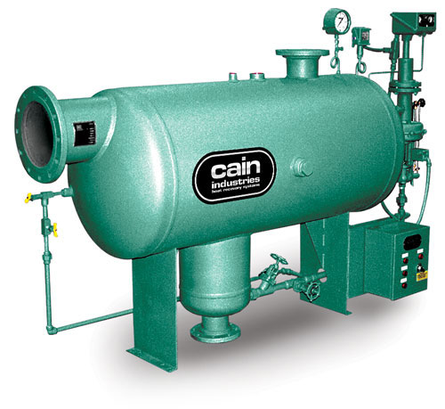
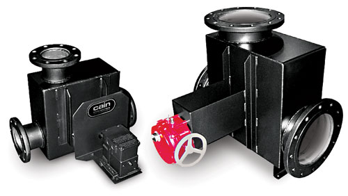
Heat Recovery Silencer Radial Series – HRSR
Heat Recovery Silencer Axial Series – HRSA
U-Tube Heat Recovery Series – UTR
(cogeneration units shown from left to right)
“Manufacturing Waste Heat Transfer Products To Save Energy”
Since 1978, Cain Industries has dedicated itself to producing exclusively, combustion exhaust heat transfer products. Our successful experience with lowering fuel costs and reducing pollution makes us the first choice for both the retrofit and OEM client.
We set ourselves apart from the competition by producing products to serve the broad spectrum of the combustion retrofit markets: Diesel and Gas Cogeneration, Boiler Exhaust, and Fume Incineration. The knowledge we gain from each market helps the continuing improvement of the others. As the only manufacturer capturing these three markets, we have developed the greatest selection of products to precisely fit within their particular system applications. Coupled with our heat transfer programs and CAD engineered designs, we have developed fifteen product lines with over 2,350 pre-designed industrial heat transfer models.
We are also especially dedicated to a primary investment in our associates with their manufacturing technology, quality improvements, and innovative cost reductions. As a result, our customers can expect competitively priced products aimed at having the greatest return on their investment along with the longest lasting equipment.
The basic philosophy which Cain Industries has built its success and reputation upon is: "Produce the highest quality products and provide unmatched customer satisfaction."
John Cain
President & CEO
Cain Industries is 10 miles northwest of Milwaukee, Wisconsin and 30 minutes from General Mitchell International Airport.
THE HEAT TRANSFER SYSTEMS FOR ENGINE EXHAUST RECOVERY
INTRODUCTION
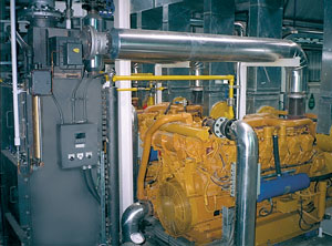
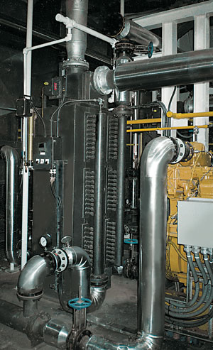
Cain Industries offers an extensive selection of cogeneration systems specifically designed for gas and diesel engine, gas turbine and micro turbine generator retrofit applications. We offer over 500 standard products to choose from and will provide a comprehensive analysis and quotation to fit your exact needs within 48 hours. Our equipment can be adapted and assembled to fit any application or complete installation.
- Hospitals
- Manufacturing Plants
- Schools
- Office Buildings
- Shopping Malls
- Drilling Platforms
- Oil and Gas Plants
- Marine
- Exhaust Steam Generators
- Large Exhaust Recovery Silencers
- Smaller Specialized Exhaust Recovery Silencers
- Special Heat Transfer Configurations
- Recirculating Engine Jacket Water Boilers
SYSTEM FUNCTION
BTU is transferred from the exhaust stream to heat sinks such as water, glycol, therminol fluids, or steam production. Suitable fuel types for combustion sources include natural gas, propane, digester gas, diesel fuel and light to heavy fuel oils.
- Large or irregular exhaust connections
- High or varying exhaust temperatures
- Particular pinch point requirements
- Exhaust or liquid control
- Special heat sink requirements
- Special heat transfer metallurgy requirements
- Specific maintenance concerns
- Optional equipment requirements
- Installation space and weight concerns
- Package system requirements
- Tremendous fuel savings typically pay for equipment and installation within 1 to 3 years of average use.
- Pollution reduction due to lowered annual fuel usage.
- Lower exhaust temperatures and significantly reduced sound output levels (final sound attenuation is typically 15 - 25 dBA).
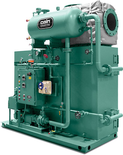
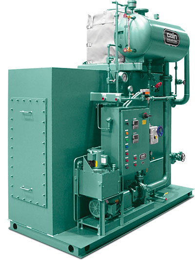
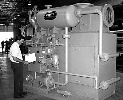
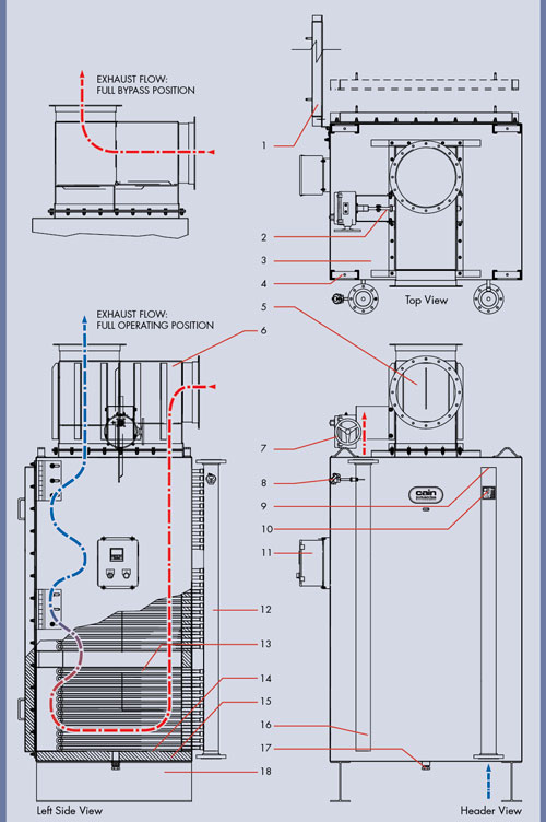
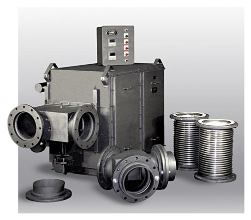
ESG1 - EXHAUST STEAM GENERATOR
The fully packaged ESG1 is selected from 124 pre-engineered standard models with output capabilities of 20 to 300 boiler hp and operating steam pressures from 3 to 450 psig. The ESG1 is shipped complete, ready for operating as either a primary or supplementary steam source.
Full operating steam pressure from a cold start in less than 10 minutes.
The ESG1 package is made up of three basic sections:- Finned tube heat transfer section
- Steam flash circulating drum assembly
- Modulating full port exhaust bypass system
- Capacity: 400kW – 7MW
- Entering gas temps: 500 – 1,250°F
- Heat sink types: Supplemental steam demand and/or primary steam source for steam heating or process steam.
OPERATION & CONTROL
The integral forced circulating water pump continually circulates high temperature water from the steam flash drum assembly to the heat transfer core assembly. BTU is transferred from the exhaust to a high flow superheated water/steam mixture. The superheated water is returned to the steam drum which contains dry pipe, baffles, and lance assemblies, where it flashes into 99% dry stream as its exits out to the system.
As the water is generated into steam and exits the boiler, the modulating boiler feedwater system controls continuous feedwater flow for constant drum water level control. Fail safe controls are built in for full exhaust bypass in the event of electrical or pneumatic loss.
The steam pressure controller maintains the operating steam pressure as it controls the modulating exhaust bypass assembly. This provides solid operating steam pressure under various operating steam load demands.
QUALITY CONTROL
The ESG1 is manufactured, tested, and stamped in accordance with the requirements of Section I of the ASME Boiler and Pressure Vessel Code, and National Board. Boiler trim includes all safety controls and alarms to meet state and federal codes. Final assembly, electrical wiring, and factory adjustments are completed under a strict set of guidelines.
The ESG1 is an easy choice when compared to the "old technology" of a conventional firetube boiler:
- Completely self-contained package design reduces engineering, installation, and maintenance costs.
- Size requires only 1/2 the floor space and 1/2 the weight of conventional boilers, which reduces building size, structural support costs, and shipping costs.
- Ease of tube replacement requires no overhead cranes, special rigging, special crews, or extra roof height above the unit, while reducing down time.
- Many shapes and sizes are available to fit limited space and maintain performance requirements.
- Produces greater than 99% dry steam.
- Provides 100% turndown capability.
- 5–10 minutes from startup to full output.
- Integrated exhaust modulating bypass for safe automatic steam control.
- Explosion-proof heat transfer exchanger.
- Low friction loss for minimum static exhaust back pressure.
- High circulating flow to minimize scale buildup.
- No thermal expansion concerns with cold boiler feedwater.
- Performance aimed at the lowest pinch point in the industry (final leaving exhaust temperature minus operating steam temperature) for maximum thermal efficiency.
The ESG1 requires only the following connections for a cost effective installation:
- Steam Outlet
- Exhaust Flange Inlet and Outlet
- Single Main Power
- Single Main Blowdown
- Feedwater Inlet
- Pneumatic Control Air
- Cooling Water Inlet and Outlet
Automatic Sootblower
Sootblowers are available either as a manual push button start or fully automatic with timed sequencing. Sootblowers are considered when firing with fuel oil and/or incomplete combustion. Sootblowers are also considered when manual cleanings are not feasible in order to maintain peak performance.
Continuous Blowdown with Intermittent Conductivity Sampling Assembly
Maximize boiler efficiency by periodically sampling surface blowdown water and controlling total dissolved solids. Maintaining optimal levels of concentrations will control the costs of water, energy, and chemicals. Assembly includes: motorized valve, probe, and piping assembly.
Hinged Access Door for Full Heating Surface Inspection
Hinged access doors are considered when firing with fuel oil and/or incomplete combustion requiring full access on a regular basis for manual cleaning. A hinged access door can be incorporated for 100% finned tube viewing and attention.
Hospital, Renton, Washington
(4) Model ESG1-616B19CSS: Recovering BTU from (4) Jenbacher JMS-320, 900kW natural gas engines. Reducing each 2,498 SCFM from 977°F to 392°F. Delivering 1,863 pph steam @ 90 PSI operating (150 PSIG design).
Hospital, Chicago, Illinois
(3) Model ESG1-616B18CS: Recovering BTU from (3) Waukesha 3516, 1,100kW natural gas engines. Reducing each 2,392 SCFM from 1,135°F to 438°F. Delivering 2,173 pph steam @ 130 PSI operating (150 PSIG design).
Water Purification Plant, Burlington, Ontario
Model ESG1-A12D18CSS: Recovering BTU from a Caterpillar 3516, 800kW natural gas engine. Reducing 2,382 SCFM from 770°F to 344°F. Delivering 1,277 pph steam @ 130 PSI operating (150 PSIG design).
FOR: THE COMPLETE STEAM GENERATION PACKAGE
ASME & NATIONAL BOARD STAMPED – SECTION 1
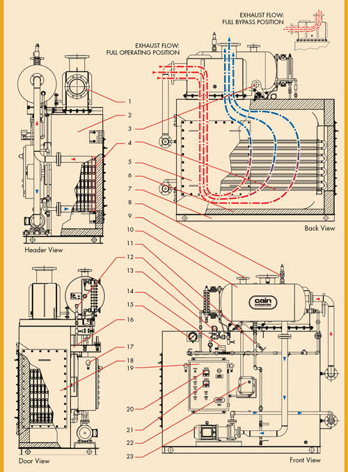
- Modulating exhaust bypass
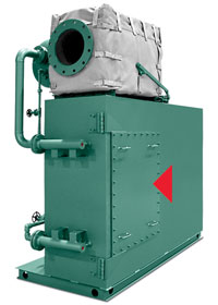
- 10 gauge carbon steel exterior
- Lifting eye
- Finned tube heat transfer section (removable finned tube rack assembly)
- Main inspection door
- High temperature insulation block
- Structural steel base
- ASME Steam safety valve
- Steam outlet flange
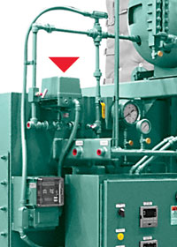
- Steam flash drum assembly (insulated)
- Main blowdown valve assembly
- Continuous surface blowdown
- Differential pressure, water level controller
- Modulating feedwater valve
- Steam pressure gage
- Localized piping connections for feedwater and blowdown manifold
- Excess steam pressure switch
- Tube removal access door
- NEMA 12 control panel complete: High voltage 3 phase single connection, fuse disconnect, circulating pump variable speed drive, step down transformer, alarm lights
- Digital modulating water level controller
- Digital steam pressure controller
- Modulating damper actuator
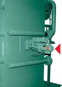
- Magnetic circulating pump assembly
Testing of all components, electrical controls, and hydrostatics as a system, is completed prior to shipment, insuring a smooth and efficient field startup.
Final inspection, under the strict guidelines of Cain Industries and ASME quality control standards, is conducted for each unit.
Complete packaged units are shipped for immediate installation upon arriving on site.
Field startup and operator training is realized quickly with factory trained personnel.
The following is a general specification, shown as a guide for design and construction.
1.0 General Design:
1.1
The ESG1 shall be a packaged forced circulation coil design, manufactured and tested in accordance with the requirements of Section 1 of the ASME Boiler and Pressure Vessel Code, and stamped at 150 PSIG (15 to 450 PSIG available) to the appropriate Section. The operating pressure shall be ______PSIG.
1.2
The ESG1 shall have the capacity to operate automatically as a supplemental or primary steam generator. It shall be designed to produce full steam output in approximately 10 minutes from a cold start and to operate fully automatic under fluctuating steam loads and/or exhaust volumes.
2.0 General Construction:
2.1
The design shall be made up of three basic sections mounted on a structural steel skid, pre-piped, wired for ease of installation, requiring no field assembly.
2.2
The sections shall include a finned tube heating surface, modulating full port exhaust bypass, and steam flash drum assembly as standard components.
2.3
An integral circulating pump shall also serve to circulate water from the heat transfer section back to the steam flash drum assembly.
2.4
All water, air, and blowdown connections shall be localized within a common manifold assembly for ease of the piping installation.
2.5
Exhaust volume connections shall be located at the top of the ESG1 for ease in exhaust piping installation.
3.0 Heat Exchanger Section:
3.1
Explosion-proof heating surface to be nickel brazed/welded fin to tube for high heat transfer and corrosion protection (.109 wall thickness x .030 minimum fin thickness).
3.2
The finned tubing shall be designed in multiple sections for ease of replacement.
3.3
The heat exchanger section shall contain a main inspection door for tube removal and a main inspection access port for cleaning and/or inspection.
3.4
The reinforced enclosure shall contain 304 stainless steel baffles with 4" minimum thickness thermal insulation. The enclosure shall be designed to operate with exhaust temperatures entering @ 1,250°F maximum (1600°F design available) and shall have a gas tight seal with continuously welded 10ga. carbon steel exterior: Design Pressure (exhaust side): 10 inches water column, primed/painted with high temp. metallic paint.
4.0 Modulating Bypass Assembly:
4.1
The modulating bypass assembly shall be constructed of minimum .25" thickness plate steel (stainless steel available) and the exhaust connections shall be 150 lb. design SA105 exhaust flanges, when applicable. The bypass assembly shall be bolted to the heat exchanger section for ease of maintenance. Insulation shall be provided by others as needed.
4.2
The bypass shall be controlled by a modulating pneumatic positioning actuator and steam pressure dial controller, for controlling the volume of waste heat exhaust as dependent on steam pressure.
4.3
The reinforced damper assembly shall be constructed of 304 stainless steel and designed for tight seal during the full bypass.
4.4
The 304 stainless steel damper shaft shall contain high temperature bearings and packing glands to seal exhaust leakage.
4.5
In the event of an air pressure or electrical failure to the ESG1, the modulating bypass assembly shall contain an alarm fail safe operating mode, whereby the damper assembly shall automatically move to the full exhaust bypass position.
5.0 Steam Flash Drum & Control Assembly:
5.1
The steam flash drum assembly shall contain internal baffles and dry pipes for 99% dry steam output and 1" thick thermal insulation with a minimum 16 gauge carbon steel exterior and shall include the following:
5.1.1
The ANSI standard configured circulating pump and TEFC motor shall be incorporated to maintain high water flow turbulence for minimum fouling.
5.1.2
The blowdown valving shall include a main drum blowdown valving assembly including quick opening and shut off valves, a continuous surface blowdown valve, and a water level control blowdown valve all manifolded for a single blowdown connection.
5.1.3
Safety controls to include low/high water cutout, excess steam pressure cutout, and low air pressure cutouts (for pneumatic exhaust bypass actuator).
5.1.4
The water level control system shall contain fully modulating boiler feedwater pump level control and valve assembly with boiler feedwater on/off auxiliary switch.
5.1.5
Water level control to contain red line water level sight glass with drain cock.
5.1.6
All required gauges for steam (41/2" dial minimum), feedwater, pump cooling water, and air indication (21/2" dial minimum) shall be provided.
5.1.7
(1) ASME and National Board stamped steam safety relief valve.
5.1.8
All necessary interconnecting piping linkages and valving shall be provided.
5.1.9
All inner connecting piping shall be insulated by others as required.
5.2
Control panel to be NEMA 12 construction to accept a single main power connection with main fuse disconnect and starter, fuse-protected step down transformer, power and run indicating lights, fill indicating light, low and high water alarm indicating lights, and low air and excess steam pressure lights.
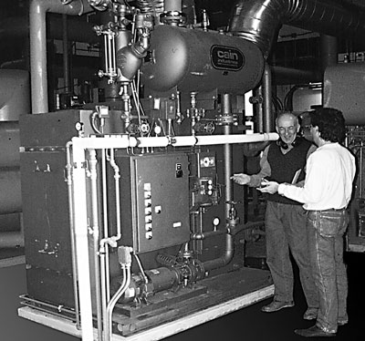
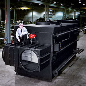
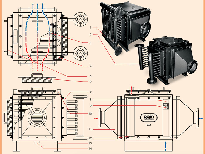
HRSR - HEAT RECOVERY SILENCER RADIAL
The HRS Radial waste heat recovery silencer is a module configuration package with 176 standard models available. It packages standard features such as: full exhaust bypass, full heating surface access, factory insulation, hard shell exterior, stainless interior, 3" thickness factory insulation, and a variety of finned tube types and fin spacings to fit the proper application. The HRSR is designed to receive the total exhaust and liquid flow from a single source and control exit temperatures to the desired performance levels. During full operation, the radial design channels the exhaust flow through an hour glass expansion flow pattern which provides for significant dBA reduction.
The full port exhaust bypass is located at the top for convenient installation. Depending on space considerations, the unit may be installed in the horizontal position as shown below. The unique configuration of the single row design heating surface allows for reduced fouling potential. The full access to the core with optional hinged doors also allows for fast routine inspection and/or manual cleaning. Finned tube replacement requires no overhead cranes, special rigging, special crews, or extra roof height above the unit. Individual finned tube replacement, if required, is fast and easy with minimum down time.
Fully packaged for micro-cogen applications through the large turbines
ENGINE EXHAUST APPLICATION- Capacity: 200kW – 7MW
- Entering gas temps: to 1,250°F
- Heat sink types: Engine jacket water, process water, boiler water or ethylene glycol
- Full exhaust gas bypass assembly
- Sound attenuation
- Stainless steel interior lining
- Internal heating surface expansion design
- No joint welds within the heating surface in contact with the exhaust gas stream
- 10 gauge hard shell seal welded exterior
- Single row design for complete and full access
- Ease of tube replacement requiring no overhead cranes or special rigging
- Liquid temperature indicating control assembly
- Hinged inspection doors for immediate access
- Timed automatic timed sootblowers
- Modulating damper actuator (pneumatic or electric)
- Compression fitted tube to header attachment requiring no welding for fin tube replacement
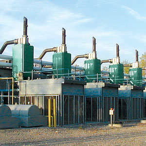
Airport, Detroit, Michigan - (3) Model HRSR-472H28CSS recovering BTU from (3) Wartsila 345G, 5.7MW natural gas engines. Reducing each 698°F @ 18,373 SCFM to 320°F. Raising 175 GPM hot water from 250°F to 350°F.
Innovative Energy Systems, Oakfield, New York - (7) Model HRSR-330C26SSP recovering 1,845,000 BTU/hr each from (7) Caterpillar 3516 engine. Reducing each 922°F to 387°F @ 2,766 SCFM; Raising 300 GPM hot water from 180°F to 194°F.
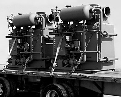
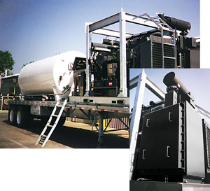
(2) Mobile Trailers, (2) Model HRSR-216826SSS recovering BTU from a diesel fueled N14 Cummins engine Reducing each 865°F @ 1,188 SCFM to 465°F. Raising 70 GPM 50% Ethylene Glycol from 70°F to 90°F.
Gold & Silver Mine, Eskay Creek, British Columbia - (3) Model HRSR-316A26CSP recovering BTU from (3) Caterpillar 3512, 900kW diesel engines. Reducing each 870°F @ 2,100 SCFM to 417°F. Raising 265 GPM 50% ethylene glycol from 187°F to 197°F.
Hospital, Ontario - (2) Model HRSR-336B28CSS recovering BTU from (2) Cummins Wartsila CW180, natural gas engines. Reducing each 968°F @ 3,666 SCFM to 339°F. Raising 175 GPM hot water from 195°F to 229°F.
FOR: LARGE ENGINES & FULL FEATURE DESIGN
ASME & National Board stamped – Sec.VIII, Div.1
- Inspection door assembly, for finned tube inspection, clean out or removal (optional hinged version)
- Stainless steel damper shaft
- 10 gauge thickness exterior
- Lifting lug
- Stainless steel bypass damper
- Exhaust bypass assembly
- Modulating actuator (optional pneumatic or electric)
- Thermocouple
- 3/4" NPT vent
- ASME stamp (optional)
- Control panel (used with Automatic Sootblower Assembly and/or Liquid Temperature Control - optional)
- Header manifold (low liquid pressure drop)
- Finned tube* assembly (single row design for complete access to heating surface)
- Stainless steel interior
- 3" thick insulation
- 3/4" NPT drain
- 11/2" NPT cleanout
- H-Beam support
Available fin type: carbon steel, TP304 stainless, aluminum
Methods of attachment: nickel brazed, welded, Al-Fuse
TIMED AUTOMATIC SOOTBLOWER (optional)
Traveling nozzle rings and concentrated spray provide superior sootblower cleaning.
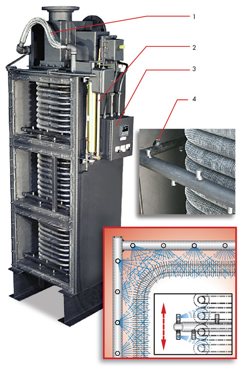
The exclusive Cain Industries Timed Automatic Sootblower design is applied to combustion sources where the sulfur content is high and/or combustion efficiency is poor. When a soot layer accumulates on the heating surface to a thickness of 1/8", fuel consumption is increased by 8.5%. The sootblower is also applied when it is not cost-effective to open inspection doors and clean the exchanger by other means. The sootblower system will continually keep the heating surface at a high performance level and eliminate the day-to-day operator expense and engine down time.
The blowdown sequence occurs while the engine is in full operation and is fully adjustable. The special flood-jet type nozzles achieve maximum cleaning velocity using steam or air as discharged through an electric control valve (included). Together they form a 'continuous knife edge concentrated spray pattern' surrounding the heating surface. This 'ring nozzle assembly' as attached to a manifolded flexible steel hose assembly, is powered up and down by a pneumatic drive cylinder. Dual timing relays allow complete control for 30 second cycle duration and intervals specific to each application. Final results are controlled double cleaning action, insuring that the maximum BTU recovery and anticipated savings are achieved.
SOOTBLOWER ASSEMBLY- Flexible Steam Hose with Actuated Steam Valve(steam or air inlet connection)
- Pneumatic Drive Cylinder (1/4 NPT air 80 psig connection)
- NEMA 12 Control Panel (single 120v. 60hz 1ph power connection)
- Traveling Nozzle Ring Assemblies
LIQUID TEMPERATURE CONTROL (optional)
Operating Sequence: During a cold startup the exhaust bypass will be powered to the normal operating position. As the liquid temperature rises and approaches a preset point, the exhaust bypass damper will begin to move to the temperature control position. When the desired temperature is completely satisfied the damper actuator will move to the maximum open position, bypassing 99% of the exhaust flow (100% bypass cannot be attained due to some leakage and residual heat in contact with the fin tubing). Included is a 4-20 mA output controller, thermocouple, thermocouple weld and wire, and modulating bypass actuator installed, wired, and tested for a single 120 volt, 1ph, 60hz power connection.
A general specification, shown as a guide for design & construction.
1.0 General Design:
1.1
Furnish and install a heat recovery silence radial unit (HRSR); an exhaust heat recovery unit in accordance with the following specifications as designed and manufactured by Cain Industries, Inc.
1.2
The HRSR shall be of a rectangular, continuous seal welded structural reinforced design with an all stainless steel interior lining. (optional all stainless steel construction available for No 6 oil, biogas, landfill gas, & digester gas exhaust applications)
1.3
The HRSR shall be designed to include as standard, an external Exhaust Gas Bypass assembly, with stainless steel construction (optional) and flanged, exhaust gas connections for liquid temperature control and/or full emergency exhaust bypass.
1.4
The HRSR shall have a hinged, full face, gas tight, inspection door providing access to the entire heating surface for inspection, tube removal, and/or cleaning.
1.5
The HRSR must be completely drainable when mounted in the vertical or horizontal position.
1.6
Header manifolds for low liquid flow pressure drop shall be provided and shall have connections, screwed or flanged as specified. Liquid inlet and outlet pipe connections greater than 2" shall be flanged. The liquid header manifolds shall also contain 3/4" NPT connections for venting, draining, and/or safety relief valves as required.
1.7
The design of the vessel itself shall be such that no tube to tube or tube to header joint welds shall be in contact with the exhaust stream, thereby minimizing potential vessel failure.
1.8
The fin tubing shall be in a single row arrangement for inspection and/or ease of cleaning.
1.9
Compression fitted fin tubes shall be connected to header manifolds located exterior of the exhaust stream (including special exterior shell tube to exhaust seals) for ease of tube replacement, requiring no welding.
2.0 Construction:
2.1
Design Pressure:150 PSIG @ 550°F.; Test Pressure: 225 PSIG; Max. Flue Gas Inlet Temperature: 800°F for 3" thickness insulation; 900°F for 4" thickness insulation;1200°F for 6" thickness insulation
2.2
Fins: 304 stainless steel x .020" thickness, nickel brazed to the tube (optional carbon steel fin x .030" thickness)
2.3
Tube: outside diameter: 1.0"; wall thickness: .065"; Material: Type 316 stainless steel (alternate SA178 grA carbon steel x .085" wall thickness)
2.4
Headers: thickness: Sch 80; material: SA53 GrB
2.5
3-6" thickness, as required, factory installed, high temperature insulation shall be included, less the liquid headers.
2.6
Exterior shell of the heat exchanger section shall be continuous seal welded 10 gauge and the inner casing shall be 304 stainless steel and snoop pressure tested at 10" W.C.
2.7
Special codes (optional): design specifications of ASME Code: Section VIII Div. 1; ‘UM', ‘U' or Section 1 with the ‘S' symbols and National Board registered; CRN
2.8
Optional Liquid Temperature Control Assembly shall be provided, including a modulating actuator, thermocouple, controller, and electrical panel. The exhaust gas bypass is automatically modulated to control the temperature of the heated liquid leaving the heat exchanger. The controller has a continuous temperature display, an alarm output (high temp.), a 4-20mA auxiliary output signal, and MODBUS/TCPIP communications. The thermocouple will be dual element. The bypass actuator has a position feedback signal which is wired to the electrical panel. The electrical panel will be UL approved.
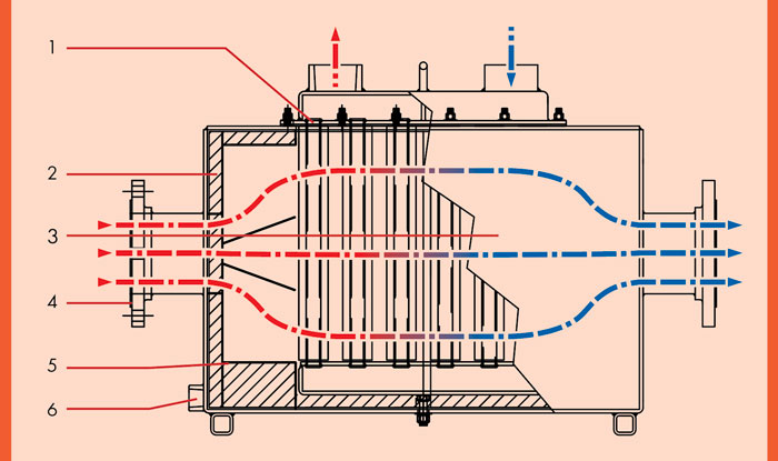
UTR-1 - U-Tube Recovery 1

The UTR1 is applied primarily where confined area restrictions vs. heat transfer requirements must be considered as a priority to the combined features of the HRSR. Its compact industrial design allows for maximum BTU recovery relative to the space allotted for installation. Finned tube spacings range from bare tube heating surface up through 8 fins per inch, depending on the fouling factor requirements. Standard fin to tube attachment using the nickel braze/weld fin to tube process allows no fin to tube separation to 2,000°F.
The UTR1 can be located above the engine or on the floor for convenient installation. With over 170 standard configurations to choose from, the UTR1 can be designed to meet the closest pinch point requirements when installation space is not an issue. Easy access allows for quick removal of finned tube rows or core assemblies without disturbing the exhaust gas connections and allows for routine inspections and/or cleaning requirements.
ENGINE EXHAUST APPLICATION- Capacity: 200kW – 10MW
- Entering gas temps: to 1,600°F
- Heat sink types: Process water, boiler feedwater, ethylene glycol or thermal transfer fluids
- Inspection doors for easy access/cleaning
- Exterior exhaust gas bypass and actuator assemblies
- Exhaust piping to UTR1 transitions
- Rotating Sootblowers (automatic/manual)
FOR: LARGE ENGINE & COMPACT DESIGN
- Parallel piping flow arrangement for high liquid flow.
- Series piping flow arrangement
Fin Tube Rack Assemblies (spaced for accessible cleaning)
– Tube materials: carbon steel, TP316 stainless
– Fin materials: carbon steel, TP304, aluminum
– Methods of finned tube attachment: nickel brazed, Al-Fuse, welded - Factory Insulation (optional): 2" - 6" thickness available
- Inspection door, fin tube removal
- Inspection door (optional), heating surface cleaning
- 10 gauge carbon steel exterior, seal welded
- 3/4" NPT vent
- ASME stamp (optional)
- Lifting lug
- Exhaust transition (optional)
- 3/4" NPT drain
- H-Beam support
- 11/2" NPT condensate cleanout drain (optional)
UTR - U-TUBE RECOVERY
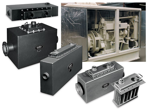
The UTR is applied where both rectangular configuration and heat transfer surface vs. performance is critical. The UTR can be located within the engine to meet crucial space limitations. There are 44 standard models available for selection to fit the most compact of spaces. With flexible exhaust gas connection sizes and locations, the UTR can adapt easily to an OEM packager's design needs. The capability of removing the core assembly without disturbing the exhaust gas connections makes cleaning and inspecting the finned tubing efficient. This is especially important when the combustion is a fuel oil type and could foul the heating surfaces.
The rugged heat transfer core is made from SA178 boiler tubing and .25" thickness high grade carbon steel heater assemblies. The heat transfer materials can also be constructed of all stainless steel when exhaust temperatures entering exceeds 1250°F or when liquid temperatures entering are below 120°F.
ENGINE EXHAUST APPLICATION- Capacity: 15 – 300 kW
- Entering gas temps: 400 to 1,600°F
- Heat sink types: Engine jacket water, ethylene glycol, process water or boiler water
- Exterior exhaust gas bypass and modulating actuator assemblies
Removable core makes cleaning and maintenance easy.
Mobile Trailer, Venice, California Model UTR-630218CSS. Recovering BTU from a 33kW natural gas engine. Reducing 1,282°F @ 76 SCFM to 319°F; Raising 27 GPM 50% ethylene glycol from 190°F to 198°F.
FOR: SMALL ENGINE COMPACT DESIGN & HIGH LIQUID FLOW
- Removable finned tube core assembly (spaced for accessible cleaning)
– Tube materials: carbon steel, TP316 stainless
– Fin materials: carbon steel, TP304 stainless
– Method of attachment: nickel brazed - Factory insulation: 1, 2 or 4" thickness (optional)
- Carbon steel shell .25" thickness
- Exhaust connections: flange, butt or NPT
- Stainless steel interior
- 1" NPT condensate cleanout drain (optional)
HRSA - HEAT RECOVERY SILENCER AXIAL
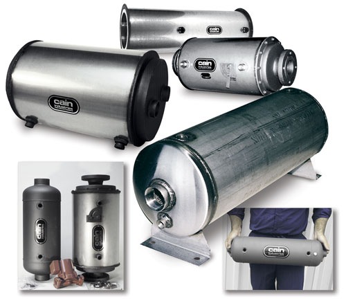
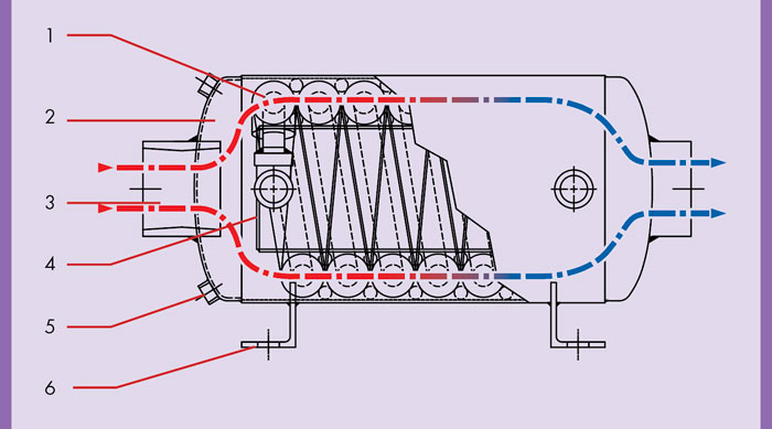
Specifically designed for small engine sizes, the HRSA waste heat recovery silencers are compact cylindrical heat exchangers designed for either dual or single exhaust small engines. There are 65 standard models available to meet the specific design-performance criteria. In addition to lowered exhaust noise, the unique coil type configuration and optional circulating pump allows for a secondary circulating liquid flow system. 1" NPT interconnecting piping, to and from a main liquid flow loop, provides for simple and less costly special piping modification changes. The required heat transfer surface coupled with a small water flow diversion from the main flow adequately recovers desired BTU/hr performance and controlled outlet exhaust temperatures as required. An optional internal or external stainless steel exhaust bypass can also allow tempering or full control of the exit temperature when required.
The HRSA design utilizes full counter flow heat transfer for achieving very low outlet exhaust gas temperatures. All stainless steel construction for specific condensing applications is available. The HRSA can be mounted vertically or horizontally as required. The HRSA with its light weight construction and cylindrical configuration, lowers the exhaust from 1000°F to 300°F with a 25 dBA reduction while operating with natural gas or diesel fuel oil.
ENGINE EXHAUST APPLICATION- Capacity: 15–150 kW
- Entering gas temps: 400–1,600°F
- Heat sink types: Engine jacket water, process water, boiler water or ethylene glycol
FOR: COMPACT CYLINDRICAL DESIGN
- Stainless or carbon steel fin tube coil: (optional fixed or removable, ASME stamp)
- Carbon steel shell, .13" thickness. (optional stainless and/or factory insulation)
- Exhaust connections: flange, butt or NPT
- Stainless steel diverter drum (optional internal exhaust bypass)
- Condensate drain (vertical or horizontal position)
- Mounting brackets for vertical or horizontal operation
OPTIONAL SYSTEM EQUIPMENT
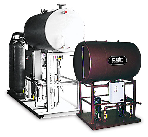
The Exhaust Cooling Steam Generator (ECSG) as designed to produce low pressure steam (15 PSIG and under) from engine jacket water via natural circulation. They are available in a variety of tank sizes for horizontal or vertical installations. Standard design includes: ASME stamped steam flash tank built in accordance with Sec.VIII Div.I; shipped as a packaged unit including continuous water level feed control with low water cutoff, auxiliary low water cutoff, excess steam pressure switch, gauge glass assembly, surface and main blowdown assembly, vent valve, steam safety valve, steam pressure gauge, wall or floor mount. Basic customer connections for ease of installation include: 150# steam outlet, 150# water outlet, 150# water/steam inlet, NPT Blowdown, and NPT Boiler feedwater. The unit shall be pre-piped and wired for a single 120v 1ph 60hz customer power connection.
Cain Boiler feedwater systems are available in a variety of tank sizes, feedwater pump configurations, and optional water treatment assemblies. Packaged assemblies include: heavy wall tank as mounted on a 5' high rectangular tube structural steel stand with water level controls and low water cutout, gauge glass and thermometer, magnesium anode; (2) 2" NPT vents; 2" NPT condensate return; 1" NPT drain with shut off valve; Duplex or Triplex boiler feedwater pump system; electrical control panel fully pre-wired with fused disconnect switches, magnetic starters, manual start-stop switches and indicating run lights for feedwater pumps and alarms; all interconnecting wiring from electrical control panel to each component, optional chemical feed system, and/or automatic water softening system; all interconnecting bypass piping, valves, gauges, fittings, etc. Primed, painted, and tested package is a complete, properly functioning assembly, ready for the customer's primary connections of water, condensate return, and electricity.
Cain Industries offers total exhaust gas control with high temperature modulating bypass and shut off valves. The valve assemblies offer precise exhaust temperature control and/or the design capability for exhaust isolation. Sizes ranging from 4" to 40" diameter are available in carbon steel and stainless steel for all engine temperatures. All valves are available with either electric or pneumatic control actuation and emergency fail safe features.
Cain Industries' engineering team is available to propose the proper system components at competitive pricing. Upon review of your application, you can expect our proposal within 24 hours. It will include professionally engineered details showing equipment costs, savings analysis, computer generated economizer performance, CAD dimensional drawings, flow schematics, warranty, and a performance guarantee.
No matter how small the micro-turbine or how large the engine, Cain Industries has the heat transfer equipment, optional components, and years of experience to provide the best solution.
- Remote digital indicators and control packages
- Pre-piped skid mounted circulation pump system packages
- Boiler blowdown assemblies
- Valves: shut off, relief, vent, drain and check
- Steam stop and check valves
- Pressure or temperature control valves
- Bi-metallic or mercury thermometers
- Expansion joints
- Explosion hatch relief ports
- Tanks: storage or expansion
- Bypass damper actuators: pneumatic or electric, on/off or modulating, air or spring failsafe return
SAVINGS COMPARISON ANALYSIS
Four examples of typical combustion source types, and the results with a Cain Industries heat recovery system applied.
| DATA without a Cain System | PERFORMANCE with a Cain System | |||
| 200 HP Steam Boiler | FCR-1L2A16ALS | |||
| Heat Sink | Return Water | Liquid Flow Rate | 15 gpm | |
| Waste Exhaust Temp. | 405°F | Final Exhaust Temp. | 249°F | |
| Water Temp. Inlet | 130°F | Water Temp. Outlet | 175.2°F | |
| BTU/hr Burner Input | 8,185,000 | Pressure Drop, Water | 2.8 psig | |
| Fuel Type | Natural Gas | Pressure Drop, Exhaust | 0.09" WC | |
| O2 Content | 5% | BTU/hr Recovered | 332,000 | |
| Excess Air | 28% | BTU/hr Saved | 406,100 | |
| Combustion Efficiency (relative) | 81.8% | Total Cost Installed | $16,801 | |
| Fuel Cost Per Therm | $0.50 | |||
| Annual Operating Hours | 6,000 | Payback: | 16.5 mo. | |
| Annual ROI: | 73% | |||
| Annual Savings: | $12,182 | |||
| Life Expectancy Savings: $243,640 (20 years) | ||||
| DATA without a Cain System | PERFORMANCE with a Cain System | |||
| 800 BHP Steam Boiler | RTR-160H26ALS | |||
| Heat Sink | Boiler Feed Water | Boiler Feed Water Flow | 55.2 gpm | |
| Waste Exhaust Temp. | 470°F | Final Exhaust Temp. | 335°F | |
| Water Temp. Inlet | 210°F | Water Temp. Outlet | 257.7°F | |
| BTU/hr Burner Input | 33,580,000 | Pressure Drop, Water | 2.0 psig | |
| Fuel Type | Natural Gas | Pressure Drop, Exhaust | 0.47" WC | |
| O2 Content | 6% | BTU/hr Recovered | 1,267,000 | |
| Excess Air | 36% | BTU/hr Saved | 1,588,100 | |
| Combustion Efficiency (relative) | 79.75% | Total Cost Installed | $37,700 | |
| Fuel Cost Per Therm | $0.80 | |||
| Annual Operating Hours | 6,000 | Payback: | 5.9 mo. | |
| Annual ROI: | 202% | |||
| Annual Savings: | $76,229 | |||
| Life Expectancy Savings: $1,524,580 (20 years) | ||||
| DATA without a Cain System | PERFORMANCE with a Cain System | |||
| 1,250 kW Engine | HRSR-336B28CS | |||
| Heat Sink | 50% Ethylene Glycol | Circulating Liquid Flow | 175 gpm | |
| Waste Exhaust Temp. | 968°F | Final Exhaust Temp. | 330°F | |
| Water Temp. Inlet | 195°F | Water Temp. Outlet | 232.3°F | |
| SCFM | 3,667 | Pressure Drop, Water | 8.3 psig | |
| Fuel Type | Natural Gas | Pressure Drop, Exhaust | 1.75" WC | |
| O2 Content | N/A | BTU/hr Recovered | 2,864,000 | |
| Excess Air | N/A | BTU/hr Saved | 3,671,400 | |
| Combustion Efficiency (relative) | 78% | Total Cost Installed | $57,960 | |
| Fuel Cost Per Therm | $0.80 | |||
| Annual Operating Hours | 6,000 | Payback: | 3.9 mo. | |
| Annual ROI: | 304% | |||
| Annual Savings: | $176,227 | |||
| Life Expectancy Savings: $3,524,540 (20 years) | ||||
| DATA without a Cain System | PERFORMANCE with a Cain System | |||
| 1,700 kW Engine | ESG1-620D18CSS | |||
| Heat Sink | Process Steam | Operating Steam Pressure | 150 PSIG | |
| Waste Exhaust Temp. | 783°F | Final Exhaust Temp. | 428°F | |
| Water Temp. Inlet | N/A | Boiler Horsepower | 68 BHP | |
| SCFM | 5,222 | Equivalent Evaporation | 2,339 pph | |
| Fuel Type | Natural Gas | Pressure Drop, Exhaust | 1.55" WC | |
| O2 Content | N/A | BTU/hr Recovered | 2,269,000 | |
| Excess Air | N/A | BTU/hr Saved | 2,909,000 | |
| Combustion Efficiency (relative) | 78% | Total Cost Installed | $113,600 | |
| Fuel Cost Per Therm | $0.80 | |||
| Annual Operating Hours | 6,000 | Payback: | 9.8 mo. | |
| Annual ROI: | 123% | |||
| Annual Savings: | $139,635 | |||
| Life Expectancy Savings: $2,792,700 (20 years) | ||||
Savings comparison data is based on a conservative fuel cost per therm (100,000 BTU), and approximate annual operating hours. Your results may vary. Total Cost Installed includes: Equipment, shipping and complete installation. Contact Cain Industries for your FREE savings analysis proposal.