EXHAUST HEAT RECOVERY
Boiler Economizer Systems
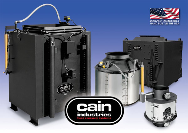
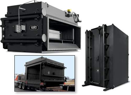
Fin Coil Recovery Series – B/FCR
Condensing Economizer Series – CXL/DXL
Energy Manager Series – EM
(boiler economizers shown from left to right)
“Manufacturing Waste Heat Transfer Products To Save Energy”
Since 1978, Cain Industries has dedicated itself to producing exclusively, combustion exhaust heat transfer products. Our successful experience with lowering fuel costs and reducing pollution makes us the first choice for both the retrofit and OEM client.
We set ourselves apart from the competition by producing products to serve the broad spectrum of the combustion retrofit markets: Diesel and Gas Cogeneration, Boiler Exhaust, and Fume Incineration. The knowledge we gain from each market helps the continuing improvement of the others. As the only manufacturer capturing these three markets, we have developed the greatest selection of products to precisely fit within their particular system applications. Coupled with our heat transfer programs and CAD engineered designs, we have developed fifteen product lines with over 2,350 pre-designed industrial heat transfer models.
We are also especially dedicated to a primary investment in our associates with their manufacturing technology, quality improvements, and innovative cost reductions. As a result, our customers can expect competitively priced products aimed at having the greatest return on their investment along with the longest lasting equipment.
The basic philosophy which Cain Industries has built its success and reputation upon is: "Produce the highest quality products and provide unmatched customer satisfaction."
John Cain
President & CEO
Cain Industries is 10 miles northwest of Milwaukee, Wisconsin and 30 minutes from General Mitchell International Airport.
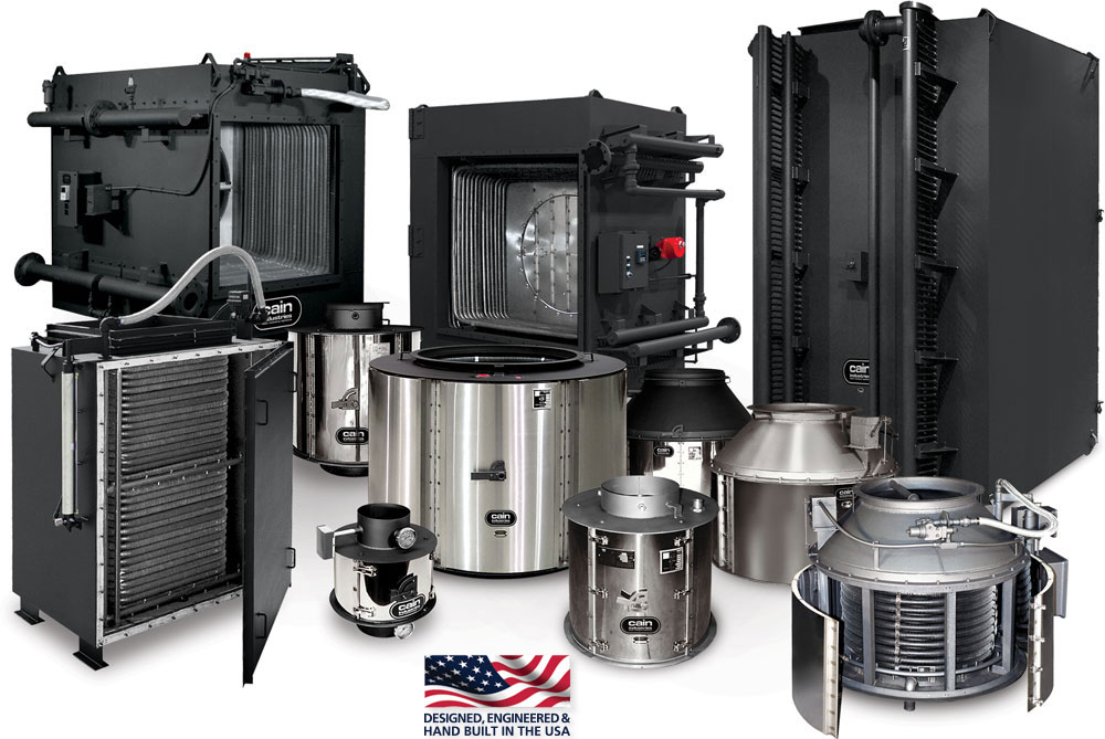
THE HEAT TRANSFER PRODUCT FAMILY FOR BOILER EXHAUST RECOVERY
INTRODUCTION
Cain Industries offers an extensive selection of boiler economizers specifically designed to recover the lost heat exiting from exhaust stacks and preheat water. Our broad line of economizers covers the spectrum of boiler sizes, ranging from very small hot water boilers with burner inputs of 200,000 BTU/hr to large boilers delivering steam at 250,000 lb/hr. In addition, Cain produces boiler feedwater systems, condensate tank and pump systems, exclusive sootblower assemblies, and unique modulating internal exhaust gas bypass systems.
- Steam Boilers
- Hot Water Boilers
- Hot Oil Heaters
- Ovens and Dryers
- Specific Combustion Sources
- Boiler Economizers
- Sootblowers
- Circulating System Components
- Storage Tanks
- Modulating Internal Exhaust Gas Bypass Assembly
SYSTEM FUNCTION
Exhaust heat from combustion typically leaving the stack and into the atmosphere is instead transferred from the exhaust stream by means of a Cain economizer. This lost BTU is now captured and saved to various heat sinks such as boiler feedwater, cold makeup water, process water, swimming pool water, glycol, and thermal fluids. Combustion source fuel types including natural gas, propane, digester gas, diesel fuel, and No.2-6 fuel oil are all heat sources which can be retrofitted with Cain heat exchangers.
PROPOSAL CONSIDERATIONS
Consider Cain for cylindrical or rectangular stack connections, large or small boilers, a particular pinch point requirement, stack or liquid temperature control, special heat sink requirements, special heat transfer metallurgy requirements, specific maintenance concerns, optional equipment requirements, installation space and weight concerns, and package system requirements.
- Tremendous fuel savings typically pay for equipment and installation within 1 to 2 years of average use
- Pollution reduction equivalent to lowered annual fuel usage
- Longest heat exchanger life expectancy
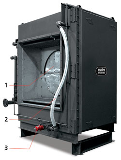
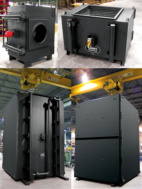
RTR - RECTANGULAR TUBE RECOVERY SERIES
The RTR is ideal for large steam boilers and hot water boilers. The RTR is typically used to preheat boiler feedwater, process water, hot oil, or cold water condensing applications. A variety of heat transfer surfaces are available, including: 316L stainless steel, carbon steel, duplex stainless steel, and stainless steel tube with aluminum bonded AL-FUSE™ product (see the example RTR product specification for materials). The exclusive, standard feature, internal stainless steel exhaust gas bypass can be used to temper the exiting gas for stack corrosion control or to maintain water temperatures when too much heat is available.
BTU/hr input to 250,000,000 - Entering exhaust temps to 800°F
COMBUSTION SOURCES
Steam boilers, hot water boilers, and hot oil heaters with inputs up to 250,000,000 BTU/hr.
- Capacity: to 250,000 lb/hr steam
- Entering gas temps: 300°F – 800°F
- Heat sink types: Boiler feedwater, makeup water, hot water return, hot water storage tank, condensate tank, process water
 FEATURES
- Internal expansion design
- Most models have no pressure welds in the gas stream
- Mounting flanges for bolting to mating flanges/adapters
- Condensate drain catch ring assembly
- 10 ga. structural exterior
- Stainless steel interior
- 2" factory insulation
- Removable access doors
- Stainless steel bypass
- Header manifold for high liquid flow
- Exclusive Cain compression fittings between finned tubes and the liquid manifolds for easy tube removal that requires no welding
- Internal stainless steel bypass diverter controls either exiting exhaust gas or liquid temperatures
- Flexible stainless steel hose allows travel of the sootblower carriage
- Sootblower controller maintains air/steam pressure during blowdown operation
- Modulating bypass actuator assembly for automatic operation
- Hinged inspection doors for immediate access
- Timed automatic sootblower assembly provides blowdown without scheduling personnel
- Stack corrosion control assembly
- Liquid temperature control assembly
- Structural support stand
Ethanol Plant, Oshkosh, Wisconsin RTR-166K25.7ALS recovering BTU from a 2,200 BHP, steam boiler; Reducing 367°F @ 18,473 SCFM to 299°F; Raising the temperature of 152 gpm of boiler feedwater from 227°F to 245°F.
Installation: structural support stand
Ice Cream Plant, Bakersfield, California RTR-148F26ALS recovering BTU from a 500 BHP, steam boiler; Reducing 430°F @ 4,198 SCFM to 305°F; Raising the temperature of 35 gpm of boiler feedwater from 210°F to 247°F.
Installation: ceiling suspension
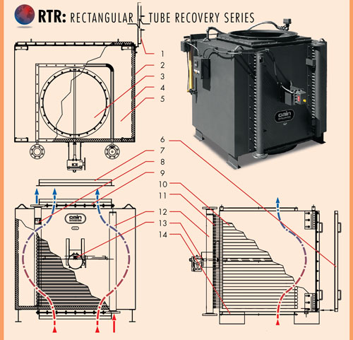
- Optional hinged door
- 10 ga. carbon steel exterior
- Stainless steel exhaust gas bypass
- 2" thick insulation
- Stainless steel interior
- Inspection door for tube cleaning
- Optional RTR-to-stack adapter
- Optional ASME stamp
- 2" x 2" gas flange connection
- Removable finned tube rows
- Compression fittings for easy tube removal
- Header manifold
- Optional modulating actuator
- Optional condensate drain catch assembly
INSTALLATION FOR EXACT FIT
In many cases, the RTR is designed to replace a competitor's unit. The RTR will meet or exceed the old performance and at the same time fit within the original stack connections.
Brewery, Ontario, Canada
(1) RTR-1V2Q28CSS recovering BTU from (1) 95,000 pph steam boiler; Re educing 505°F @ 24278 SCFM to 333°F; Raising 196 gpm boiler feedwater entering at 225°F to 278°F.
VARIETY
One feature of the RTR product line is the large variety of sizes and configurations that are available. Cain Industries routinely produces RTR models that range in application size from small 50 hp boilers to massive 250,000 pph boilers. In addition, RTR units can be engineered to function in a horizontal or vertical stack and can be outfitted with optional automatic sootblowers.
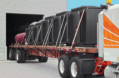
DELIVERY
Cain Industries keeps strict control over production and delivery scheduling so our customers receive their heat recovery equipment on time and on budget. We routinely ship regionally, nationally, and internationally and keep you informed every step of the way.
A general specification, shown as a guide for design & construction. (see Engineering Sales Manual for detailed specification data sheets)
1.0 General Design:
1.1
Furnish and install a rectangular tube recovery (RTR) in the exhaust duct of the boiler in accordance with the following specifications as designed and manufactured by Cain Industries, Inc.
1.2
The RTR shall be a light weight design for easy installation, rectangular with crossflow heat transfer design manufactured and tested in accordance with the requirements of Section VIII, Division 1 of the ASME Boiler and Pressure Vessel Code, and stamped to a minimum 250 PSIG design pressure to the appropriate section.
1.3
Each RTR shall be designed to include as standard, a stainless steel, internal, Flue Gas Bypass Diverter to provide for full emergency by-pass, requiring no additional ductwork for controlling: 1. Stack corrosion, 2. Turn down performance, 3. Back pressure.
1.4
The RTR shall have removable, gas-tight inspection doors providing complete access to the entire heating surface for inspection, tube removal, and/or cleaning (optional hinged doors available).
1.6
The RTR must be capable of being drained completely when mounted in the vertical or horizontal position.
1.7
Header manifolds for low liquid flow pressure drop shall be provided and shall have connections, threaded or flanged as specified. Liquid inlet and outlet pipe connections greater than 2" NPT shall be flanged. The liquid header manifolds shall also contain 3/4" NPT connections for venting, draining, and/or safety relief valves as required.
1.8
The design of the vessel itself shall be such that no tube to tube, or tube to header joint welds shall be in contact with the exhaust stream so as to minimize potential vessel failure.
1.9
The finned tubing shall be a single row design (maximum 2 row depth in the direction of the exhaust flow) for ease of cleaning and inspection. Tube to header joint shall be compression tube fittings requiring no welding for fast/easy tube replacement.
2.0 Construction:
2.1
Design Pressure (water side): 250 PSIG @650°F.; Test Pressure: 375 PSIG; Max. Flue Gas Inlet Temperature: (see below); Design Pressure (exhaust side): 3" water column
Tube & Fin Designs:
- SA178GrA ERW x 1.0" OD x .083" wall thickness with carbon steel .030 Fin thickness x .50 Hgt Nickel Brazed/welded to the tube.
- TP316L x 1.0" OD x .065" wall thickness with aluminum .020 fin thickness x .50 hgt AL-FUSE™ bonded to the tube.
- TP316L x 1.0" OD x .065" wall thickness with 304 stainless steel .020 Fin thickness x .50 Hgt Nickel Brazed/welded to the tube.
2.3
Compression fitting design: 1000 PSI @ 400°F.
2.4
Headers: thickness: Sch 80; material: SA106 GrB
2.5
2" thickness factory installed, high temperature insulation shall be contained within the exterior less the liquid headers.
2.6
Exterior surfaces shall be 10ga. carbon steel seam welded and the inner casing shall be 304 stainless steel.
2.7
Special codes (optional): design specifications of ASME Code Section VIII Division I; 'UM', 'U', or 'S' symbol; National Board registered; CRN.
3.0 Optional System Component Equipment:
(see Engineering Sales Manual for optional equipment specifications or contact Cain Industries)
EXHAUST STACK ADAPTERS allow the RTR to provide maximum heat recovery while mating perfectly with an existing exhaust stack. Adapters also allow the rectangular RTR to work with a round exhaust stack.
REMOVABLE ACCESS DOORS provide a complete view of the finned tube heating surface for inspection, repair, or maintenance. This reduces down time and labor expenses.
MOUNTING FLANGES & ADAPTERS are integral to Cain Industries economizers, reducing installation time and providing a superior connection between the existing stack and the Cain unit.
EXTERIOR LIQUID MANIFOLDS
maintain very low liquid pressure drop, eliminating the need for extra pumps/HP. This manifold is connected to the finned tubes with compression fittings which allow a finned tube to be removed for inspection or replacement without requiring any welding.
SINGLE ROW FINNED TUBING design (maximum of 2 rows in the path of the exhaust flow) allows full access to the entire heating surface and provides ease of cleaning and maintenance. Each finned tube row has no welds in the exhaust gas stream which greatly minimizes the chance of tube failure.
BYPASS DIVERTER allows the amount of exhaust gas diverted through the economizer to be modulated to achieve desired heat recovery. This becomes an important safety feature when you recover more heat than required by the existing system.
Photo on left:
Vertical flow RTR shown with optional timed automatic sootblower assemblies. This unit uses three sets of traveling carriages with high velocity cleaning nozzles.
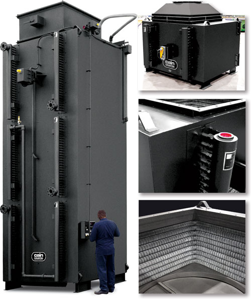
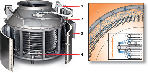
The exclusive Cain Industries Timed Automatic Sootblower design is applied where sulfur content is high or combustion is poor. The special flood-jet type nozzles achieve maximum cleaning velocity using steam or air discharged through an electric control valve. Together they form a 'continuous knife edge concentrated spray pattern' surrounding the heating surface. This 'ring nozzle assembly' is attached to a manifolded flexible steel hose assembly and is powered back and forth by a pneumatic drive cylinder. Dual timing relays allow full control of cycle duration and interval. Cleaning the finned tubing ensures maximum BTU recovery and maximum cost savings. Fouled finned tubing can reduce heat recovery by up to 50%.
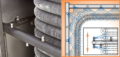
Proper sootblowing is necessary when fuel has a high sulfur content or combustion is poor (such as No. 6 fuel oil). Without sootblowing, the finned tubing will become fouled and the maximum heat recovery cannot be achieved.
The traveling Ring Assembly with Flood-Jet Nozzles, form a unique high velocity knifing action to allow full penetration of the complete heating surface. The Cain Industries sootblowing system is unsurpassed in the marketplace for effectiveness and efficiency.
Built-in timing relays allow you to customize the interval and duration to suit your application.
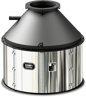
FCR - FIN COIL RECOVERY SERIES
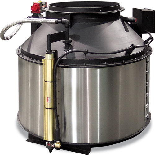
The FCR is a custom-designed heat exchanger which can be applied in confined areas and is offered in stainless steel, carbon steel, or AL-FUSE™ finned tubing. Design flexibility allows specific engineering requirements to be met such as fin spacing for fouling conditions and low gas pressure drops.
Custom designed to meet space and performance demands
FCR photo shown with optional sootblower assembly
COMBUSTION SOURCES
Steam boilers, hot water boilers, hot oil heaters, combustion sources with round stack diameters 4"-36" and a maximum liquid flow rate of 50 gpm.
- Capacity: 40 – 500 BHP (50 –10,000 SCFM)
- Entering gas temps: to 800°F
- Heat sink types: Boiler feedwater, process water, thermal fluids, run-around systems
- Internal thermal expansion design
- Cylindrical heat transfer coil(s) design
- Mounting flanges for bolting to mating flanges
- Quick release tension latches
- Stainless steel internal bypass
- Condensate drain catch ring assembly
- Hinged stainless steel access door panels
- Exclusive manual or timed automatic ring-type sootblower assembly
- Stack corrosion control assembly including temperature-regulated modulating exhaust gas bypass and remote indicators
- Circulating pump kit to maintain desired liquid flow rate
- Vertical pressurized storage tank, to create a "bulge" or temporary heat sink in the event of no-water-flow conditions
- Liquid temperature control assembly including temperature-regulated modulating exhaust gas bypass and remote indicators
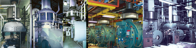
Waste Water Treatment Plant, Fond du Lac, Wisconsin
(2) FCR-1J2D25ALS each recovering BTU from (2) 150 BHP steam boilers; Reducing 700°F @ 1603 SCFM to 246°F; Raising 18 gpm boiler feedwater entering at 100°F to 201°F.
 | Printing Facility, Lomira, Wisconsin (2) Model: FCR-1L2C16ALS each Recovering BTU from a 500 BHP steam boiler; Reducing 400°F @ 4205 SCFM to 252; Raising 34.5 gpm boiler feedwater entering at 120°F to 164°F. |
FCR: SPECIFICATION
A general specification, shown as a guide for design & construction. (see Engineering Sales Manual for detailed specification data sheets)
1.0 General Design:
1.1
Furnish and install economizers on each of the combustion sources (boilers, hot water heaters, hot oil heater, etc.) as designed and manufactured by Cain Industries, Inc.
1.2
The Economizer shall be a light weight design for easy installation, cylindrical with counterflow heat transfer design manufactured and tested in accordance with the requirements of Section VIII, Division 1 of the ASME Boiler and Pressure Vessel Code, and is stamped to a minimum 250 PSIG design pressure.
1.3
Each Economizer shall be designed to include as standard, a stainless steel, internal, Flue Gas Bypass Diverter to provide for full emergency by-pass, requiring no additional ductwork for controlling:
1. Stack corrosion, 2. Turn down performance, 3. Back pressure.
1.4
Each Economizer shall have continuous hinged, gas-tight, stainless steel inspection panels, which provide for complete access to the entire heating surface for inspection and/or cleaning. The inspection panels shall be secured by adjustable, quick release tension latches and no tools shall be required for the opening of the inspection panels.
1.5
Heat Recovery unit shall be either a single, multiple, or parallel coil design and must be completely drainable when mounted vertically.
1.6
Header manifolds, where used, shall be SA53 GrB schedule 80 or SA105, connections shall be threaded or flanged as specified.
1.7
Exterior surfaces other than stainless steel shall be primed and painted with a high temperature metallic paint rated for 1000°F.
2.0 Construction:
2.1
Design Pressure (water side): 250 PSIG @650°F.; Test Pressure: 375 PSIG; Max. Flue Gas Inlet Temperature: (see below); Design Pressure (exhaust side): 3" water column
2.2
Tube & Fin Designs:
- SA178GrA ERW x 1.0" OD x .083" wall thickness with carbon steel .030 Fin thickness x .50 Hgt Nickel Brazed/welded to the tube. (Max. Flue Gas Inlet Temperature: 800°F)
- TP316L x 1.0" OD x .065" wall thickness with aluminum .020 fin thickness x .50 hgt AL-FUSE™ bonded to the tube. (Max. Flue Gas Inlet Temperature: 750°F)
- TP316L x 1.0" OD x .065" wall thickness with 304 stainless steel .020 Fin thickness x .50 Hgt Nickel Brazed/welded to the tube. (Max. Flue Gas Inlet Temperature: 800°F)
2.3
Headers: thickness: Sch 80; material: SA53 GrA and/or 2000# Forged Steel
3.0 Optional System Component Equipment:
(see Engineering Sales Manual for optional equipment specifications or contact Cain Industries)
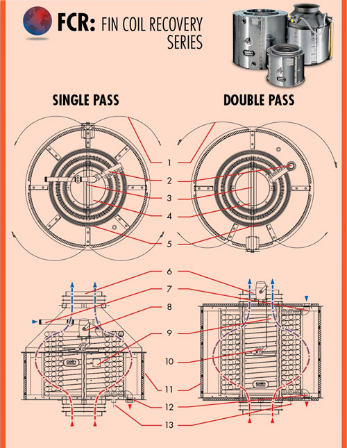
- Stainless steel doors with self-locking tension latches
- Liquid inlet
- Diverter shaft
- Stainless flue gas bypass
- Finned tube coil assembly
- Mating flange
- Liquid inlet
- Optional modulating bypass actuator assembly
- Optional ASME stamp
- Manual bypass assembly
- Optional insulation
- Liquid outlet
- Optional condensate drain catch assembly
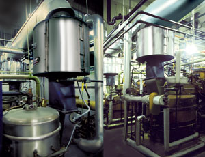
A Cain Industries FCR boiler economizer can often be installed in-line with your existing stack, resulting in a relatively quick and cost-efficient installation process with minimal retrofitting, labor, materials, and down time. Generally, because of their lighter weight and smaller size, the FCR requires little, if any, additional support (usually suspended from the ceiling). In applications where additional support is required, Cain Industries can offer a structural support stand. Economical in-line installation - another Cain Advantage.
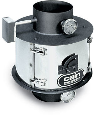
B SERIES
The B Series boiler economizer is comprised of 14 standard models. An "off the shelf" unit, it is designed primarily for boilers with round stacks and a combustion capacity of 40 to 800 BHP with entering gas temperatures between 300° and 700°F. The standard stack connections can be easily modified to fit specific boiler stacks with 10" to 34" diameters, alleviating the cost of stack adapters. The units come standard either with 4 or 6 fins per inch (fpi) spacings for operation with No. 2 fuel oil and/or natural gas and depending on the efficiency of the combustion. With its lightweight design and exclusive AL-FUSE™ heat transfer surface, installation is fast and costs are kept to a minimum. Use the chart on the next page to select the B Series unit that is best suited to your application.
• Minimum Cost • Easy Installation • Maximum Savings
B Series single-pass unit shown with stack adapter cone
COMBUSTION SOURCES
Steam boilers and hot water boilers
- Capacity: 40 – 800 BHP
- Entering gas temps: 300°F – 700°F
- Heat sink types: Boiler feedwater, hot water return, hot water storage tank, condensate tank, process water
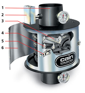
- Hinged stainless steel access door panels
- Internal thermal expansion design
- Mounting flanges for bolting to mating flanges or adapters
- Stainless steel internal exhaust bypass assembly
- Quick release tension latches for doors
- Optional sootblower assembly
With the variety of boiler room sizes, coupled with limited space, horizontal or vertical installations, can be accommodated with the cylindrical B Series or FCR economizer product lines.
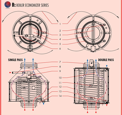
- Stainless steel doors with self-locking tension latches
- Liquid inlet
- Diverter shaft
- Stainless flue gas bypass
- Finned tube coil assembly
- Liquid inlet
- Mating flange
- Liquid inlet
- Optional modulating bypass actuator assembly
- Optional ASME stamp
- Manual bypass assembly
- Optional insulation
- Liquid outlet
- Optional condensate drain catch assembly
| B SERIES MODEL SELECTION | |||||||||||||
| Model | BHP | H.S. | Ft2 | Dia. | Height | Weight in LBS | Stack Flange Conn. | Water Conn. NPT | Sootblower Conn. | Drain Catch Ring Conn. | Total Weight w/Insulation & Stblr. | ||
| 6FPI | 4FPI | ID | B.C. | Qty. Holes | |||||||||
| B04 | 40 | 91 | N/A | 30 | 15.5 | 175 | 12 | 14 | 8 | 1 | N/A | 1/2 | 210 |
| B07 | 70 | 126 | N/A | 30 | 19.5 | 190 | 12 | 14 | 8 | 1 | N/A | 1/2 | 250 |
| B10 | 100 | 72 | 119 | 36 | 23.5 | 220 | 12 | 14 | 8 | 1 | N/A | 1/2 | 300 |
| B12 | 125 | 218 | 151 | 36 | 27.5 | 260 | 16 | 18 | 8 | 1 | N/A | 1/2 | 345 |
| B15 | 150 | 263 | 182 | 36 | 31.5 | 300 | 16 | 18 | 8 | 1 | N/A | 1/2 | 390 |
| B20 | 200 | 384 | 265 | 42 | 24.5 | 350 | 20 | 213/4 | 12 | 11/4 | 1 | N/A | 450 |
| B25 | 250 | 486 | 336 | 42 | 28.5 | 390 | 20 | 213/4 | 12 | 11/4 | 1 | N/A | 490 |
| B30 | 300 | 635 | 440 | 48 | 30.0 | 440 | 24 | 257/8 | 12 | 11/2 | 11/4 | N/A | 550 |
| B35 | 350 | 720 | 498 | 48 | 32.0 | 485 | 24 | 257/8 | 12 | 11/2 | 11/4 | N/A | 600 |
| B40 | 400 | 805 | 557 | 48 | 34.0 | 550 | 24 | 257/8 | 12 | 11/2 | 11/4 | N/A | 645 |
| B50 | 500 | 932 | 645 | 48 | 38.0 | 590 | 24 | 257/8 | 12 | 11/2 | 11/4 | N/A | 700 |
| B60 | 600 | 1059 | 733 | 48 | 42.9 | 650 | 30 | 323/8 | 16 | 11/2 | 11/4 | N/A | 760 |
| B70 | 700 | 1186 | 821 | 48 | 46.0 | 690 | 30 | 323/8 | 16 | 11/2 | 11/4 | N/A | 830 |
| B80 | 800 | 1313 | 909 | 48 | 50.0 | 750 | 30 | 323/8 | 16 | 11/2 | 11/4 | N/A | 890 |
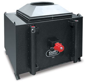
EM - ENERGY MANAGER SERIES
The EM is designed to recover heat from combustion sources with atmospheric burners from 200 to 6,400 MBH. Ten standard models are designed to operate with low static gas pressure drop for safe, automatic operation on atmospheric, or power burners.
Built to rigid ASME quality control standards
EM Series package includes all basic control hardware for simplified installation.
COMBUSTION SOURCES
Steam boilers, hot water boilers, dryers and ovens
- Capacity: 200,000 – 6,400,000 BTU/hr input
- Entering gas temps: 300°F – 700°F
- Heat sink types: Boiler feedwater, hot water return, hot water storage tank, condensate tank, process water
- Built to rigid ASME quality control standards
- Highest heat transfer efficiency with AL-FUSE™ finned tubing
- Quick release access door latches for ease of maintenance/inspection
- Packaged design includes all basic control hardware to properly operate unit in the field
- Adjustable internal stainless steel exhaust gas bypass
- Guaranteed heat recovery performance
- Slip-fit gas connections
- Temperature Controlled Pump controller
- Internal stainless steel bypass to modulate heat recovery as needed
- Single row finned tubing for maximum efficiency and ease of cleaning
- Quick-release tension latches do not require tools
- Stainless Steel hinged access panels minimize labor and downtime during inspection, cleaning, or repair
Includes circulating pump package: In-line circulating pump, inlet and outlet temperature gauges, check valve, relief valve, flow control valve and differential pump control
College Campus, Long Beach, California
(10) EM Series boiler economizers preheating hot water return loops.
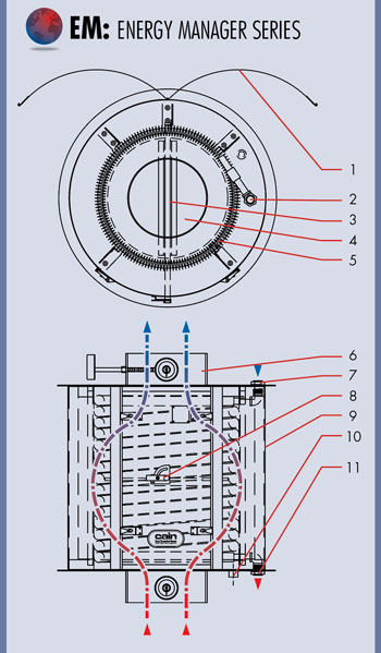
EM ASSEMBLY
- Stainless steel doors with self-locking tension latches
- Liquid inlet
- Diverter shaft
- Stainless flue gas bypass
- Finned tube coil assembly
- Slip-fit gas connection
- Liquid inlet
- Manual bypass assembly
- Optional insulation
- Optional condensate drain catch assembly
- Liquid outlet
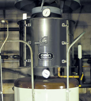
Condominium Complex, Milwaukee, Wisconsin
EM Series economizer, on top a domestic hot-water heater, preheating municipal water.
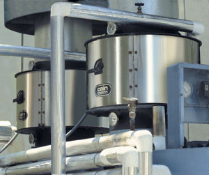
Industrial Laundry, Fresno, California
(2) EM Series, boiler economizers, preheating boiler feedwater for (2) 115 BHP Parker steam boilers.
EM SERIES MODEL SELECTION
The following model selections are determined by stack diameters and BTU/hr input using this simple selection chart. After the correct Energy Manager has been selected, contact your Cain representative to determine your fuel savings and provide a complete proposal with payback period. Stack diameters smaller than standard EM sizes can be accommodated simply with a pair of EM Model to Stack Transitions.
| Model No. | Burner Input (BTU/hr) | Stack Diameter |
| EM-6 | 200,000 | 6" |
| EM-8 | 400,000 | 8" |
| EM-10 | 600,000 | 10" |
| EM-12 | 800,000 | 12" |
| EM 14 | 1,250,000 | 14" |
| EM-16 | 1,600,000 | 16" |
| EM-20 | 2,500,000 | 20" |
| EM-24 | 3,600,000 | 24" |
| EM-28 | 5,000,000 | 28" |
| EM-32 | 6,400,000 | 32" |
CXL - SINGLE STAGE CONDENSING ECONOMIZER

The CXL Single Stage Condensing Exhaust Economizer is specifically designed to recover sensible heat from within the exhaust and, more importantly, to also recover additional valuable latent heat as the exhaust is condensed. Typically the recovered heat will be transferred to the cold makeup or process water, thereby increasing the overall efficiency and lowering the fuel demand. As the exhaust temperature is dramatically reduced to 120°F – 170°F, resulting condensation is safely captured and drained from the economizer and away from the boiler.
Recovers both sensible and latent heat increasing the overall efficiency
COMBUSTION SOURCES
Steam boilers, hot water boilers, and hot oil heaters with inputs up to 250,000,000 BTU/hr. (Natural gas fired)
- Capacity: to 250,000 lb/hr steam
- Entering gas temps: 300°F – 800°F
- Heat sink types: makeup water and process water
- Internal expansion design
- Mounting flanges for bolting to mating flanges/adapters
- Condensate drain catch ring assembly
- 12 gauge stainless steel exterior
- Stainless steel interior
- 2" factory insulation
- Removable access doors
- Stainless steel bypass
- Stainless steel header manifold for high liquid flow
- Compression fittings between finned tubes and the liquid manifolds for easy tube removal that requires no welding
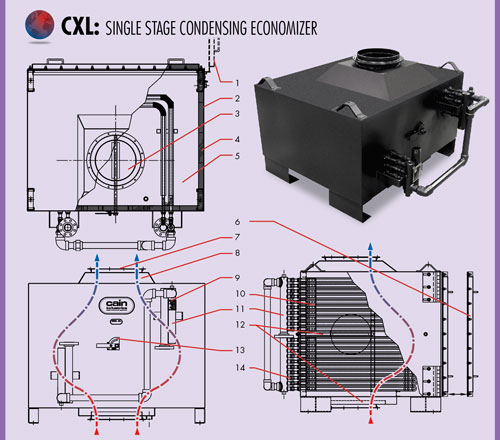
- Optional hinged door
- 12 gauge stainless steel exterior
- Stainless steel exhaust gas bypass
- 2" thick insulation
- Stainless steel interior
- Inspection door for tube cleaning
- Exhaust stack flange connection
- Optional stack to economizer adapter
- Optional ASME stamp
- Removable finned tube rows
- Header manifold
- Condensate drain catch assembly
- Manual bypass assembly
- Compression fittings for easy tube removal
DXL - TWO STAGE CONDENSING ECONOMIZER
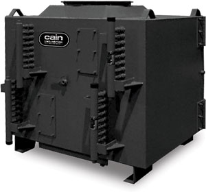
The DXL Two Stage Condensing Exhaust Economizer is specifically designed to recover sensible heat from within the exhaust and, more importantly, to also recover additional valuable latent heat as the exhaust is condensed. What makes the DXL Boiler Economizer unique is that it recovers heat in two stages. The first stage will preheat boiler feedwater and the second stage will preheat boiler make-up water. Final exhaust temperatures leaving typically range from 120°F – 170°F. This recovered heat will be transferred to feedwater and makeup water, thereby increasing the overall efficiency and lowering the fuel demand.
Preheats feedwater and makeup water for greater efficiency
COMBUSTION SOURCES
Steam boilers, hot water boilers, and hot oil heaters with inputs up to 250,000,000 BTU/hr. (natural gas fired)
- Capacity: to 250,000 lb/hr steam
- Entering gas temps: 300°F – 800°F
- Heat sink types: Boiler feedwater, makeup water, hot water return, hot water storage tank, condensate tank and process water
- Internal expansion design
- Mounting flanges for bolting to mating flanges/adapters
- Condensate drain catch ring assembly
- 12 ga. stainless steel exterior
- Stainless steel interior
- 2" factory insulation
- Removable access doors
- Stainless steel bypass
- Stainless steel header manifold for high liquid flow
- Compression fittings between finned tubes and the liquid manifolds for easy tube removal that requires no welding
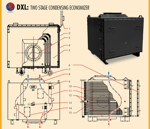
- Optional hinged door
- 12 gauge stainless steel exterior
- Stainless steel exhaust gas bypass
- 2" thick insulation
- Stainless steel interior
- Inspection door for tube cleaning
- Exhaust stack flange connection
- Optional stack to economizer adapter
- Optional ASME stamp
- Removable finned tube rows
- Header manifold
- Condensate drain catch assembly
- Manual bypass assembly
- Inspection access
- Compression fittings for easy tube removal
SYSTEM COMPONENTS
Cain Industries offers a wide range of system components, pre-engineered specifically for each application. Every product has been tested, shown to be of the highest quality, and proven to be fully compatible with all Cain heat recovery products.
MATING FLANGES, AND GASKETS
Cain offers round, square, and rectangular mating flanges, transitions, and gasket sets to suit most any application. Flanges are black steel or stainless steel where appropriate.
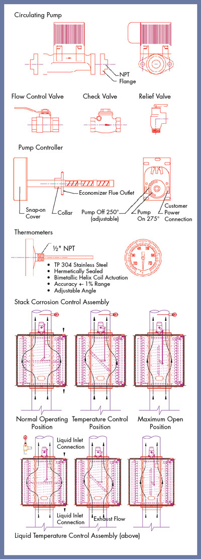
CIRCULATING PUMP KIT ASSEMBLY
Cain offers all necessary pumps and related fittings for your heat recovery application – whether you need Shut off valves, Check valves, Relief valves, Vent valves, Steam Stop valves, Pressure or Temperature Control valves, or Drain valves.
DRAIN CATCH RING ASSEMBLY
Under various applications with natural gas combustion, condensation can accumulate within the economizer and/or stack outlet. The 'drain catch ring assembly' safely collects and drains away all possible condensation. It includes various NPT drain connection sizes, depending on the application.
SUPPORT STANDS
Cain offers structural steel support stands that easily bolt together for low cost and ease of field assembly.
LIQUID TEMPERATURE CONTROL
Cain Industries offers a sophisticated liquid temperature control which functions as follows: During a cold startup, the exhaust bypass will be powered to the normal operating position. As the liquid temperature rises and approaches a preset point, the Liquid Temperature Control signals the exhaust bypass diverter which will begin to move to the temperature control position. When the desired temperature is completely satisfied, the diverter actuator will move to the maximum open position. The heat recovery can be reduced by up to 50%. Included is a 4-20mA output controller, thermocouple, thermocouple weld and wire, as well as a modulating bypass actuator installed, wired, and tested (for a single 120 volt, 1ph, 60 hz connection).
STACK CORROSION CONTROL ASSEMBLY
This assembly includes: Control panel with digital controller, modulating diverter actuator, and thermocouple. The Cain Stack Corrosion Control assembly senses a minimum exhaust gas temperature leaving the economizer. During a cold startup, the diverter will be powered to the 'Maximum Open Position.' As the temperature rises above a preset minimum temperature, the diverter will begin to close to the 'Normal Operation Position.' As the percent of exhaust load conditions fluctuate to lower outputs, the diverter actuator will open accordingly to maintain a minimum preset outlet 'Temperature Control Position.'
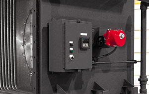
RTR Control panel shown with optional Modulating Bypass Diverter Actuator which powers the diverter to the desired position for maximum heat recovery.
CUSTOM ENGINEERING
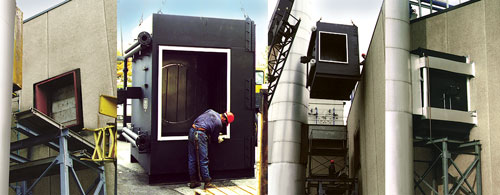
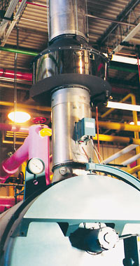
REPLACING THE COMPETITION
Beyond the 5 boiler economizer product lines, including over 500 boiler exhaust economizers, the 'unique application' is no problem. Our team concept with the specifying engineer provides the solutions for the complete engineered system. These systems have ranged from modifying the RTR model to all stainless for condensing natural gas combustion below 150°F to preheating boiler feedwater from bio/landfill fired boiler exhaust.
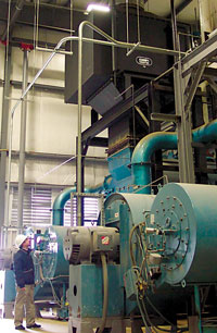
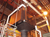
Impossible to some, but for one of the largest hospitals in Manhattan we designed and manufactured a large customized RTR unit (lower-left photo) that could be shipped in small components and reassembled in the field. The objective was to provide a boiler economizer which would retrofit the exhaust of two of the five 125,000 pph boilers as located 3 stories below the street. All the components were shipped on two flat bed trucks. Upon jobsite arrival the components were manually carried down through a 3x3 foot square manway in the middle of the sidewalk. They were then assembled together as a single 250,000 pph boiler economizer within the two boiler's manifolded exhaust breaching. Since the boiler feedwater piping had been completed prior, the installation was finished in two weeks!.
The horizontal RTR (top photo) was custom engineered and manufactured to replace a competitor's unit that failed. One of the problems causing the failure was poor performance due to an ineffective sootblower. Cain's exclusive Timed Automatic Sootblower provides total control for blowdown intervals to accommodate the specific soot buildup of every application. This unit was also designed to exactly match the exhaust flange dimensions and overall size for easy replacement.
The vertical RTR unit (upper-right photo) replaced a failed competitor's unit and was constructed to be a replacement fit and offer greater performance. ASME designed at 750 PSIG this RTR is rated for a 150,000 lb/hr steam boiler. With an exhaust gas flow rate of more than 36,000 SCFM, it saves the end user over $450,000 each year in fuel costs.
We engineer and manufacture combustion heat recovery systems for just about every type of combustion source. This ranges from the small multi-family residential natural draft boilers to the large high pressure industrial boiler feedwater preheater systems.
Whether you need a single straight forward economizer or you are planning a complex process application, we would like to discuss the ways that Cain Industries can dove-tail our engineering skills to meet your needs.
EXCLUSIVE OPTIONAL TIMED AUTOMATIC SOOTBLOWERS
The exclusive Cain Industries Timed Automatic Sootblower design is applied where the sulfur content is high and/or combustion efficiency is poor. When a soot layer accumulates on the heating surface to a thickness of 1/8", fuel consumption is increased by 8.5%. The sootblower is also applied when it is not cost-effective to open inspection doors and clean the exchanger by other means. The sootblower system will continually keep the heating surface at a high performance level and eliminate the day-to-day operator expense and operation down time.
The blowdown sequence occurs while the boiler is in full operation and is fully adjustable. The special flood-jet type nozzles achieve maximum cleaning velocity using steam or air as discharged through an electric control valve (included).
Together they form a 'continuous knife edge concentrated spray pattern' surrounding the heating surface. This 'ring nozzle assembly' is attached to a manifolded flexible steel hose assembly and powered up and down by a pneumatic drive cylinder. Dual timing relays allow complete control for cycle duration and interval specific to each application. The final results are a controlled double cleaning action, insuring that the maximum BTU recovery and anticipated savings are achieved.
- Flexible Steam Hose with Actuated Steam Valve (steam or air inlet connection)
- Pneumatic Drive Cylinder (1/4 NPT air 80 psig connection)
- NEMA 12 Control Panel (single 120v. 60hz 1ph power connection)
- Traveling Ring Nozzle Assembly
- Flood-jet type nozzles together form a unique high velocity knifing action to allow full penetration of the complete heating surface.
GENERAL APPLICATION
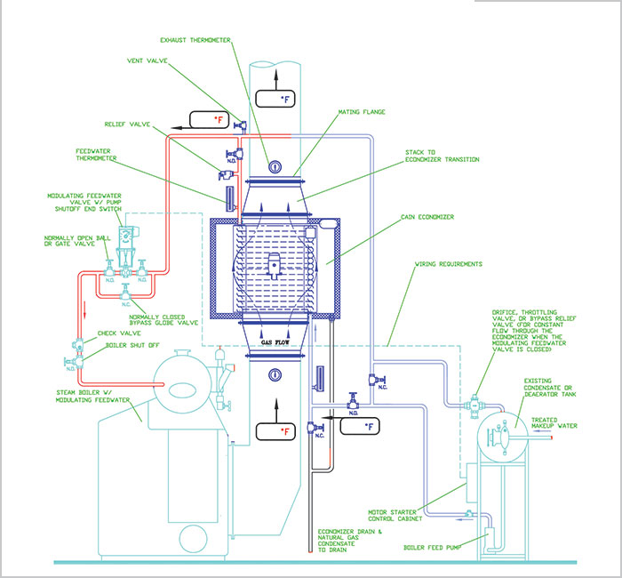
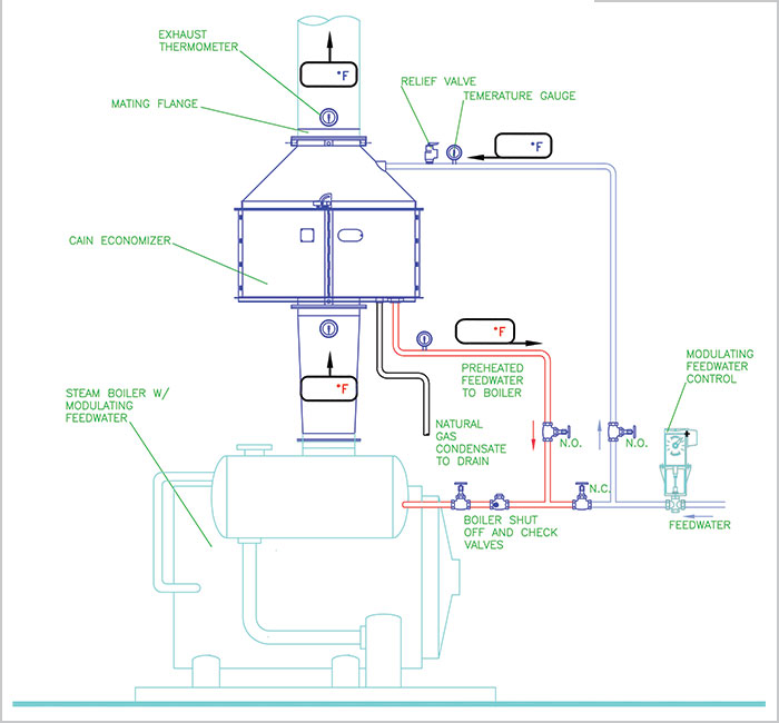
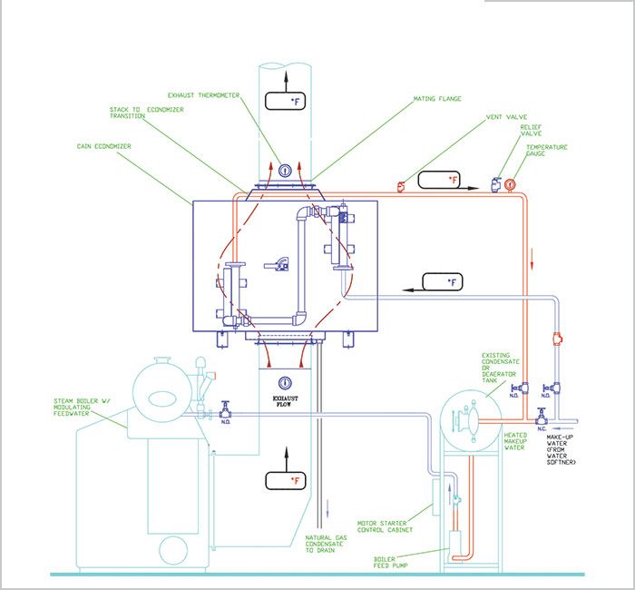
PREHEATING BOILER FEEDWATER
Steam Boiler Exhaust
For boilers with continuous, modulating feedwater.
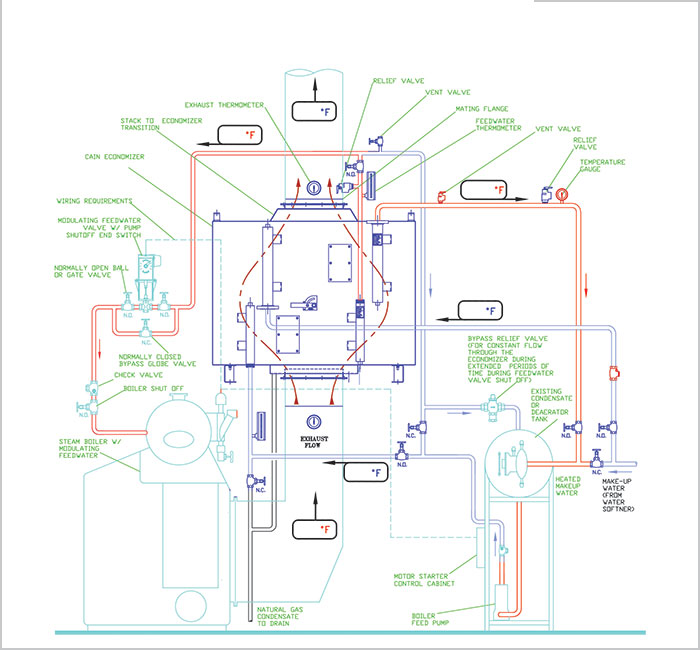
PREHEATING BOILER FEEDWATER
Firetube Steam Boiler Exhaust
For boilers with continuous, modulating feedwater.
PREHEATING BOILER FEEDWATER
Water Tube Steam Boiler Exhaust
For boilers with continuous, modulating feedwater.
PREHEATING BOILER FEEDWATER & MAKEUP WATER
Firetube or Water Tube Steam Boiler Exhaust
For boilers with continuous, modulating feedwater and cold makeup water.
(Condensing Heat Exchanger)
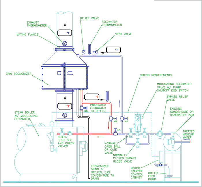
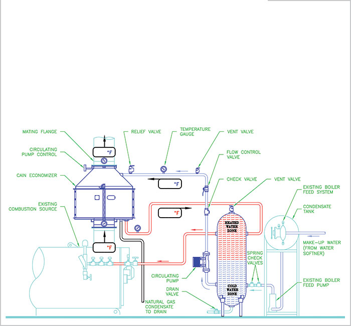
PREHEATING BOILER FEEDWATER
Steam Boiler Exhaust (Circulating tank system)
For boilers with on/off feedwater.
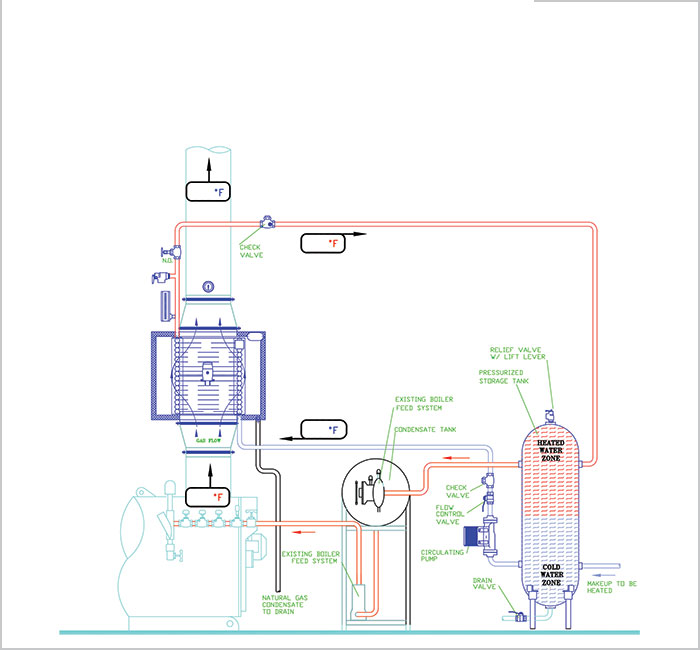
PREHEATING MAKEUP WATER
Steam Boiler Exhaust (Circulating tank system)
For boilers with on/off makeup water.
PREHEATING MAKEUP WATER
Firetube or Water Tube Steam Boiler Exhaust
For boilers with continuous, cold makeup water. (Condensing Heat Exchanger)
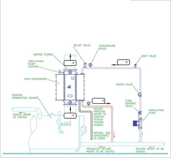
PREHEATING HOT WATER RETURN
Hot Water Boiler
SAVINGS COMPARISON ANALYSIS
Four examples of typical combustion source types, and the results with a Cain Industries heat recovery system applied.
| DATA without a Cain System | PERFORMANCE with a Cain System | |||
| 1200 BHP Steam Boiler | RTR-160H26ALS | |||
| Heat Sink | Boiler Feed Water | Boiler Feed Water Flow | 82.8 gpm | |
| Waste Exhaust Temp. | 405°F | Final Exhaust Temp. | 307°F | |
| Water Temp. Inlet | 220°F | Water Temp. Outlet | 250°F | |
| BTU/hr Burner Input | 50,212,000 | Pressure Drop, Water | 1.0 psig | |
| Fuel Type | Natural Gas | Pressure Drop, Exhaust | 0.49" WC | |
| O2 Content | 3.5% | BTU/hr Recovered | 1,210,000 | |
| Excess Air | 18.5% | BTU/hr Saved | 1,468,200 | |
| Combustion Efficiency (relative) | 82.8% | Total Cost Installed | $38,380 | |
| Fuel Cost Per Therm | $0.80 | |||
| Annual Operating Hours | 6,000 | Payback: | 6.5 mo. | |
| Annual ROI: | 184% | |||
| Annual Savings: | $70,472 | |||
| Life Expectancy Savings: $1,409,440 (20 years) | ||||
| DATA without a Cain System | PERFORMANCE with a Cain System | |||
| 800 BHP Steam Boiler | RTR-160H26ALS | |||
| Heat Sink | Boiler Feed Water | Boiler Feed Water Flow | 55.2 gpm | |
| Waste Exhaust Temp. | 470°F | Final Exhaust Temp. | 335°F | |
| Water Temp. Inlet | 210°F | Water Temp. Outlet | 257.7°F | |
| BTU/hr Burner Input | 33,580,000 | Pressure Drop, Water | 2.0 psig | |
| Fuel Type | Natural Gas | Pressure Drop, Exhaust | 0.47" WC | |
| O2 Content | 6% | BTU/hr Recovered | 1,267,000 | |
| Excess Air | 36% | BTU/hr Saved | 1,588,100 | |
| Combustion Efficiency (relative) | 79.75% | Total Cost Installed | $37,700 | |
| Fuel Cost Per Therm | $0.80 | |||
| Annual Operating Hours | 6,000 | Payback: | 5.9 mo. | |
| Annual ROI: | 202% | |||
| Annual Savings: | $76,229 | |||
| Life Expectancy Savings: $1,524,580 (20 years) | ||||
| DATA without a Cain System | PERFORMANCE with a Cain System | |||
| 1,250 kW Engine | HRSR-336B28CS | |||
| Heat Sink | 50% Ethylene Glycol | Circulating Liquid Flow | 175 gpm | |
| Waste Exhaust Temp. | 968°F | Final Exhaust Temp. | 330°F | |
| Water Temp. Inlet | 195°F | Water Temp. Outlet | 232.3°F | |
| SCFM | 3,667 | Pressure Drop, Water | 8.3 psig | |
| Fuel Type | Natural Gas | Pressure Drop, Exhaust | 1.75" WC | |
| O2 Content | N/A | BTU/hr Recovered | 2,864,000 | |
| Excess Air | N/A | BTU/hr Saved | 3,671,400 | |
| Combustion Efficiency (relative) | 78% | Total Cost Installed | $57,960 | |
| Fuel Cost Per Therm | $0.80 | |||
| Annual Operating Hours | 6,000 | Payback: | 3.9 mo. | |
| Annual ROI: | 304% | |||
| Annual Savings: | $176,227 | |||
| Life Expectancy Savings: $3,524,540 (20 years) | ||||
| DATA without a Cain System | PERFORMANCE with a Cain System | |||
| 1,700 kW Engine | ESG1-620D18CSS | |||
| Heat Sink | Process Steam | Operating Steam Pressure | 150 PSIG | |
| Waste Exhaust Temp. | 783°F | Final Exhaust Temp. | 428°F | |
| Water Temp. Inlet | N/A | Boiler Horsepower | 68 BHP | |
| SCFM | 5,222 | Equivalent Evaporation | 2,339 pph | |
| Fuel Type | Natural Gas | Pressure Drop, Exhaust | 1.55" WC | |
| O2 Content | N/A | BTU/hr Recovered | 2,269,000 | |
| Excess Air | N/A | BTU/hr Saved | 2,909,000 | |
| Combustion Efficiency (relative) | 78% | Total Cost Installed | $113,600 | |
| Fuel Cost Per Therm | $0.80 | |||
| Annual Operating Hours | 6,000 | Payback: | 9.8 mo. | |
| Annual ROI: | 123% | |||
| Annual Savings: | $139,635 | |||
| Life Expectancy Savings: $2,792,700 (20 years) | ||||
Savings comparison data is based on a conservative fuel cost per therm (100,000 BTU), and approximate annual operating hours. Your results may vary. Total Cost Installed includes: Equipment, shipping and complete installation. Contact Cain Industries for your FREE savings analysis proposal.